IRG4BC40W-SPBF International Rectifier, IRG4BC40W-SPBF Datasheet - Page 7
IRG4BC40W-SPBF
Manufacturer Part Number
IRG4BC40W-SPBF
Description
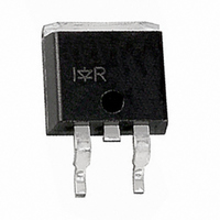
IGBT WARP 600V 40A D2PAK
Manufacturer
International Rectifier
Specifications of IRG4BC40W-SPBF
Voltage - Collector Emitter Breakdown (max)
600V
Vce(on) (max) @ Vge, Ic
2.5V @ 15V, 20A
Current - Collector (ic) (max)
40A
Power - Max
160W
Input Type
Standard
Mounting Type
Surface Mount
Package / Case
D²Pak, TO-263 (2 leads + tab)
Power Dissipation Pd
160W
Collector Emitter Voltage V(br)ceo
600V
Continuous Collector Current Ic
40A
Collector Emitter Saturation Voltage Vce(sat)
2.5V
Peak Reflow Compatible (260 C)
Yes
Rohs Compliant
Yes
Transistor Type
IGBT
Dc Collector Current
40A
Collector Emitter Voltage Vces
2.5V
Operating Temperature Range
-55°C To +150°C
Leaded Process Compatible
Yes
Lead Free Status / RoHS Status
Lead free / RoHS Compliant
Igbt Type
-
Lead Free Status / Rohs Status
RoHS Compliant part
Other names
*IRG4BC40W-SPBF
Available stocks
Company
Part Number
Manufacturer
Quantity
Price
Company:

Part Number:
IRG4BC40W-SPBF
Manufacturer:
IR
Quantity:
21 400


www.irf.com
50V
50V
R
Q
S
V
I
* Driver s am e ty pe as D .U .T.; Vc = 80% of V ce (m ax )
* Note: D ue to the 50V pow er s upply, pulse w idth a nd inductor
C
C
w ill inc rea se to obta in ra ted Id.
5 %
1 0%
Fig. 13a -
90 %
Load Test Circuit
Q
t
1 00 0V
d (o n )
Clamped Inductive
Q
1000V
10 %
L
t
r
D river*
E
V *
o n
C
R
E = (E
ts
L
o n
D .U .T.
t
d (o ff)
+E
90 %
V
o ff
C
R
)
E
t
f
o ff
I
C
0 - 480V
D .U .T.
t=5µ s
S
Fig. 13b -
Current Test Circuit
480µF
960V
Fig. 14a -
Fig. 14b -
IRG4BC40W
Pulsed Collector
* Driver same type
as D.U.T., VC = 480V
Test Circuit
Waveforms
Switching Loss
Switching Loss
R
L
=
4
X
480V
I
C
@
25°C
7
Related parts for IRG4BC40W-SPBF
Image
Part Number
Description
Manufacturer
Datasheet
Request
R

Part Number:
Description:
IGBT N-CH 600V 40A TO-220-3
Manufacturer:
International Rectifier
Datasheet:

Part Number:
Description:
IGBT WARP 600V 40A TO-220AB
Manufacturer:
International Rectifier
Datasheet:

Part Number:
Description:
IGBT WARP 600V 40A D2PAK
Manufacturer:
International Rectifier
Datasheet:

Part Number:
Description:
IGBT N-CH 600V 40A D2PAK
Manufacturer:
International Rectifier
Datasheet:
Part Number:
Description:
Manufacturer:
International Rectifier
Datasheet:
Part Number:
Description:
Insulated gate bipolar transistor. VCES = 600V, VCE(on)typ. = 1.50V
Manufacturer:
International Rectifier

Part Number:
Description:
SCHOTTKY RECTIFIER
Manufacturer:
International Rectifier Corp.
Datasheet:
Part Number:
Description:
SCHOTTKY RECTIFIER
Manufacturer:
International Rectifier Corp.
Datasheet:
Part Number:
Description:
SCHOTTKY RECTIFIER
Manufacturer:
International Rectifier Corp.
Datasheet:
Part Number:
Description:
SCHOTTKY RECTIFIER
Manufacturer:
International Rectifier Corp.
Datasheet:
Part Number:
Description:
SCHOTTKY RECTIFIER
Manufacturer:
International Rectifier Corp.
Datasheet:
Part Number:
Description:
SCHOTTKY RECTIFIER
Manufacturer:
International Rectifier Corp.
Datasheet:
Part Number:
Description:
SCHOTTKY RECTIFIER
Manufacturer:
International Rectifier Corp.
Datasheet:
Part Number:
Description:
SCHOTTKY RECTIFIER
Manufacturer:
International Rectifier Corp.
Datasheet:
Part Number:
Description:
SCHOTTKY RECTIFIER
Manufacturer:
International Rectifier Corp.
Datasheet: