IXGR35N120BD1 IXYS, IXGR35N120BD1 Datasheet
IXGR35N120BD1
Manufacturer Part Number
IXGR35N120BD1
Description
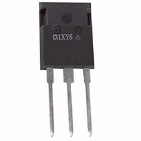
IGBT 1200V FRD ISOPLUS247
Manufacturer
IXYS
Datasheet
1.IXGR35N120BD1.pdf
(2 pages)
Specifications of IXGR35N120BD1
Voltage - Collector Emitter Breakdown (max)
1200V
Vce(on) (max) @ Vge, Ic
3.5V @ 15V, 35A
Current - Collector (ic) (max)
54A
Power - Max
250W
Input Type
Standard
Mounting Type
Through Hole
Package / Case
ISOPLUS247™
Channel Type
N
Configuration
Single
Collector-emitter Voltage
1.2kV
Gate To Emitter Voltage (max)
±20V
Package Type
ISOPLUS 247
Pin Count
3 +Tab
Mounting
Through Hole
Operating Temperature (min)
-55
Operating Temperature (max)
150C
Operating Temperature Classification
Military
Vces, (v)
1200
Ic25, Tc=25°c, Igbt, (a)
54
Ic90, Tc=90°c, Igbt, (a)
-
Ic110, Tc=110°c, Igbt, (a)
28
Vce(sat), Max, Tj=25°c, Igbt, (v)
3.5
Tfi, Typ, Tj=25°c, Igbt, (ns)
160
Eoff, Typ, Tj=125°c, Igbt, (mj)
8
Rthjc, Max, Igbt, (°c/w)
0.5
If, Tj=110°c, Diode, (a)
8
Rthjc, Max, Diode, (ºc/w)
2.5
Package Style
ISOPLUS247
Lead Free Status / RoHS Status
Lead free / RoHS Compliant
Igbt Type
-
Lead Free Status / RoHS Status
Compliant, Lead free / RoHS Compliant


High Voltage IGBT
with Diode
(Electrically Isolated Back Surface)
Symbol
(T
V
I
I
V
© 2004 IXYS All rights reserved
Symbol
V
V
V
V
I
I
I
I
SSOA
(RBSOA)
P
T
T
T
V
F
Weight
CM
CES
GES
C25
C110
F110
C
JM
GE(th)
GEM
J
stg
CE(sat)
CES
CGR
GES
C
ISOL
J
= 25°C, unless otherwise specified)
Test Conditions
I
V
V
V
I
Note 2
Test Conditions
T
T
Continuous
Transient
T
T
T
T
V
Clamped inductive load
T
50/60 Hz, RMS, t = 1 min
I
Mounting force
Maximum lead temperature for soldering
1.6 mm (0.062 in.) from case for 10 s
C
C
SOL
C
C
C
C
C
CE
GE
CE
J
J
GE
= 25°C to 150°C
= 25°C to 150°C; R
= 25°C
= 110°C
= 110°C
= 25°C, 1 ms
= 15 V, T
= 25°C
= 1mA, t = 1 s
= 250 µA, V
= V
= 0 V
= 0 V, V
= 35A, V
CES
GE
J
GE
= 125°C, R
= ±20 V
= 15 V
CE
= V
GE
GE
G
= 1 MΩ
= 10 Ω
Advanced Technical Information
T=25°C
T=125°C
IXGR 35N120BD1
min.
22...130/5...29
2.5
Characteristic Values
-55 ... +150
-55 ... +150
@0.8 V
Maximum Ratings
I
CM
typ.
2.8
= 120
1200
1200
2500
3000
±20
±30
200
250
150
300
54
28
CES
8
6
max.
±100
250
5.0
3.5
50
N/lb
V~
V~
µA
µA
nA
°C
°C
°C
°C
W
V
V
V
V
V
V
A
A
A
A
A
g
V
I
V
t
ISOPLUS247 (IXGR)
G = Gate
E = Emitter
Features
Advantages
C25
fi(typ)
Silicon chip on DCB substrate
- High power dissipation
- Isolated mounting surface
- 2500V electrical isolation
IGBT and anti-parallel FRED for
resonant power supplies
- Induction heating
- Rice cookers
MOS Gate turn-on
- drive simplicity
Fast Recovery Expitaxial Diode (FRED)
- soft recovery with low I
Saves space (two devices in one
package)
Easy to mount
Reduces assembly time and cost
CES
CE(sat)
G
C
E
= 1200 V
=
= 160 ns
= 3.5 V
C = Collector
TAB = Electrically
Isolated
54 A
DS99204(09/04)
(TAB)
RM
Related parts for IXGR35N120BD1
Image
Part Number
Description
Manufacturer
Datasheet
Request
R


Part Number:
Description:
HiPerFET Power MOSFETs
Manufacturer:
IXYS Corporation
Datasheet:
Part Number:
Description:
J-K-Type Flip-Flop
Manufacturer:
IXYS Corporation
Datasheet:
Part Number:
Description:
HiPerRF Power MOSFETs
Manufacturer:
IXYS Corporation
Datasheet:
Part Number:
Description:
Rectifier Module for Three Phase Power Factor Correction
Manufacturer:
IXYS Corporation
Datasheet:
Part Number:
Description:
Thyristor Modules Thyristor/Diode Modules
Manufacturer:
IXYS Corporation
Datasheet:
Part Number:
Description:
Thyristor Modules Thyristor/Diode Modules
Manufacturer:
IXYS Corporation
Datasheet:
Part Number:
Description:
Thyristor Modules Thyristor/Diode Modules
Manufacturer:
IXYS Corporation
Datasheet:
Part Number:
Description:
Thyristor Modules Thyristor/Diode Modules
Manufacturer:
IXYS Corporation
Datasheet:
Part Number:
Description:
Thyristor Modules /Diode Modules
Manufacturer:
IXYS Corporation
Datasheet:
Part Number:
Description:
Thyristor Modules /Diode Modules
Manufacturer:
IXYS Corporation
Datasheet:
Part Number:
Description:
Thyristor Modules Thyristor/Diode Modules
Manufacturer:
IXYS Corporation
Datasheet:
IXGR35N120BD1 Summary of contents
Page 1
... GE(th CES CE CES ± GES 35A CE(sat Note 2 © 2004 IXYS All rights reserved Advanced Technical Information IXGR 35N120BD1 Maximum Ratings 1200 = 1 MΩ 1200 GE ±20 ± 200 = 10 Ω 120 G CM @0.8 V CES 250 -55 ... +150 150 -55 ... +150 2500 3000 22...130/5...29 300 Characteristic Values min ...
Page 2
... Notes: 1. Switching times may increase for V or increased Pulse test, t ≤ 300 µs, duty cycle d ≤ IXYS reserves the right to change limits, test conditions, and dimensions. IXYS MOSFETs and IGBTs are covered by 4,835,592 one or moreof the following U.S. patents: 4,850,072 4,881,106 ...