IRGP20B120U-E International Rectifier, IRGP20B120U-E Datasheet
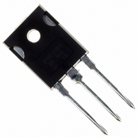
DIODE IGBT 1200V 20A TO-247AD

IRGP20B120U-E

Manufacturer Part Number
IRGP20B120U-E
Description
DIODE IGBT 1200V 20A TO-247AD
Manufacturer
International Rectifier
Datasheet

Specifications of IRGP20B120U-E

Igbt Type
NPT
Voltage - Collector Emitter Breakdown (max)
1200V
Vce(on) (max) @ Vge, Ic
4.85V @ 15V, 40A
Current - Collector (ic) (max)
40A
Power - Max
300W
Input Type
Standard
Mounting Type
Through Hole
Package / Case
TO-247-3 (Straight Leads), TO-247AD
Dc Collector Current
40A
Collector Emitter Voltage Vces
1.2kV
Power Dissipation Pd
300W
Collector Emitter Voltage V(br)ceo
1.2kV
Operating Temperature Range
-55°C To +150°C
No. Of Pins
3
Rohs Compliant
No
Lead Free Status / RoHS Status
Contains lead / RoHS non-compliant
Other names
*IRGP20B120U-E
IRGP20B120UE

Available stocks

Company
Part Number
Manufacturer
Quantity
Price
Part Number:
IRGP20B120U-E
Manufacturer:
IR
Quantity:
505
Part Number:
IRGP20B120U-E
Manufacturer:
IR
Quantity:
12 500
Part Number:
IRGP20B120U-EP
Manufacturer:
IR
Quantity:
20 000
INSULATED GATE BIPOLAR TRANSISTOR
Features
Benefits
www.irf.com
• UltraFast Non Punch Through (NPT)
• 10
• Square RBSOA
• Extended lead TO-247 package
• Benchmark efficiency above 20KHz
• Rugged with UltraFast performance
• Low EMI
• Optimized for Welding, UPS, and Induction Heating
• Significantly Less Snubber required
• Excellent Current sharing in Parallel operation
• Longer leads for easier mounting
• Positive V
Technology
applications
µ
s Short Circuit capability
Thermal Resistance
Absolute Maximum Ratings
V
I
I
I
I
V
E
P
T
T
R
R
R
Z
C
C
CM
LM
P
Wt
J
STG
CES
GE
AS
D
D
@ T
@ T
CS
JC
JC
JA
@ T
@ T
@ T
CE
C
C
(on) Temperature Coefficient
C
C
C
= 25°C
= 100°C
= 100°C
= 25°C
=25°C
Collector-to-Emitter Breakdown Voltage
Continuous Collector Current
Pulsed Collector Current
Clamped Inductive Load Current
Gate-to-Emitter Voltage
Avalanche Energy, single pulse
I
L = 200µH
Maximum Power Dissipation
Operating Junction and
Storage Temperature Range
Soldering Temperature, for 10 seconds
Mounting torque, 6-32 or M3 screw.
Junction-to-Case - IGBT
Case-to-Sink, flat, greased surface
Junction-to-Ambient, typical socket mount
Weight
Transient Thermal Impedance Junction-to-Case
C
= 25A, V
Parameter
Parameter
CC
(Fig. CT.6)
= 50V, R
GE
(Fig.3, Fig. CT.5)
= 25ohm
(Fig.2)
(Fig.2)
(Fig.1)
(Fig.1)
(Fig.4, Fig. CT.2)
G
n-channel
(Fig.18)
300, (0.063 in. (1.6mm) from case)
Min.
–––
–––
–––
–––
E
C
10 lbf•in (1.1N•m)
IRGP20B120U-E
-55 to + 150
Max.
1200
6 (0.21)
± 20
120
120
300
120
40
20
65
Typ.
0.24
TO-247AD
–––
–––
UltraFast IGBT
V
GE
V
CE(on) typ.
= 15V, I
V
CES
Max.
0.42
–––
–––
40
= 1200V
C
= 20A, 25°C
Units
Units
g (oz)
°C
°C/W
3.05V
mJ
W
V
A
V
PD- 94117
03/06/01
1

Related parts for IRGP20B120U-E

IRGP20B120U-E Summary of contents

Page 1

... Fig. CT.2) = 50V 25ohm GE (Fig. CT.6) (Fig.2) (Fig.2) 300, (0.063 in. (1.6mm) from case) Min. ––– ––– ––– ––– (Fig.18) PD- 94117 IRGP20B120U-E UltraFast IGBT 1200V CES V 3.05V CE(on) typ 15V 20A, 25° TO-247AD Max ...

Page 2

... IRGP20B120U-E Electrical Characteristics @ TJ = 25°C (unless otherwise specified) Parameter V Collector-to-Emitter Breakdown Voltage (BR)CES Temperature Coeff. of Breakdown Voltage (BR)CES Collector-to-Emitter Saturation V Voltage CE(on) V Gate Threshold Voltage GE(th Temperature Coeff. of Threshold Voltage GE(th) g Forward Transconductance fe I Zero Gate Voltage Collector Current CES I Gate-to-Emitter Leakage Current ...

Page 3

... lle rre (° ° < ° www.irf.com tio 2µ s 10µ 100µ 10m IRGP20B120U (° ° ...

Page 4

° ...

Page 5

... ° ° www.irf.com IRGP20B120U ° Fig. Trans fer C harac teris tic 20V ; tp= 20µ ° ° ° ° ...

Page 6

° µ ...

Page 7

... liz tio www.irf.com tio IRGP20B120U µ 120 160 thJC 200 ...

Page 8

Fig. CT.1 - Gate Charge Circuit (turn-off) DUT 0 1K Fig. CT.3 - S.C. SOA Circuit Driver DC DUT Fig. CT.5 - Resistive Load Circuit VCC R = ICM DUT VCC 80 V Fig. CT.4 - Switching ...

Page 9

... Fig. WF.1 - Typ. Turn-off Loss Waveform @ Tj=125°C using Fig. CT (µ www.irf.com Fig. WF.2 - Typ. Turn-on Loss Waveform Fig. WF.3- Typ. S.C. Waveform @ T =150°C using Fig. CT (µ IRGP20B120U-E @ Tj=125°C using Fig. CT (µ ...

Page 10

... IRGP20B120U-E TO-247AD Case Outline and Dimensions IR WORLD HEADQUARTERS: 233 Kansas St., El Segundo, California 90245, USA Tel: (310) 252-7105 10 Data and specifications subject to change without notice. This product has been designed and qualified for the industrial market. Qualification Standards can be found on IR’s Web site. ...

Page 11

Note: For the most current drawings please refer to the IR website at: http://www.irf.com/package/ ...

Related keywords