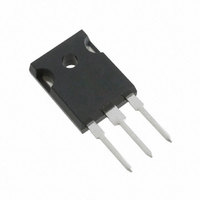
IRG7PH42UD1PBF International Rectifier, IRG7PH42UD1PBF Datasheet - Page 2

IRG7PH42UD1PBF
Manufacturer Part Number
IRG7PH42UD1PBF
Description
IGBT N-CH 1200V 85A TO-247AC
Manufacturer
International Rectifier
Datasheet
1.IRG7PH42UD1PBF.pdf
(9 pages)
Specifications of IRG7PH42UD1PBF
Igbt Type
Trench
Voltage - Collector Emitter Breakdown (max)
1200V
Vce(on) (max) @ Vge, Ic
2V @ 15V, 30A
Current - Collector (ic) (max)
85A
Power - Max
313W
Input Type
Standard
Mounting Type
Through Hole
Package / Case
TO-247-3 (Straight Leads), TO-247AC
Transistor Type
IGBT
Dc Collector Current
85A
Collector Emitter Voltage Vces
1.7V
Collector Emitter Voltage V(br)ceo
1.2kV
Operating Temperature Range
-55°C To +150°C
Transistor Case
RoHS Compliant
Package
TO-247
Circuit
Co-Pack
Switching
Soft
Switching Speed
ULTRAFAST 8-30 kHz
Vces (v)
1200
Ic @ 25c (a)
85
Ic @ 100c (a)
45
Vce(on)@25c Typ (v)
1.70
Vce(on)@25c Max (v)
2.00
Ets Typ (mj)
3.29
Ets Max (mj)
3.8
Vf Typ
1.15
Pd @25c (w)
313
Environmental Options
PbF
Lead Free Status / RoHS Status
Lead free / RoHS Compliant
IRG7PH42UD1PbF/IRG7PH42UD1-EP
Notes:
‚
ƒ
„
…
†
V
V
ΔV
V
V
gfe
I
V
I
Q
Q
Q
E
t
t
E
t
t
C
C
C
RBSOA
Electrical Characteristics @ T
Switching Characteristics @ T
CES
GES
d(off)
f
d(off)
f
(BR)CES
CES(Transient)
CE(on)
GE(th)
FM
off
off
ies
oes
res
g
ge
gc
(BR)CES
V
Pulse width limited by max. junction temperature.
Refer to AN-1086 for guidelines for measuring V
R
Calculated continuous current based on maximum allowable junction temperature. Bond wire current limit is 78A. Note that current
limitations arising from heating of the device leads may occur with some lead mounting arrangements.
Rating for Hard Switching conditions. Rating is higher in Soft Switching conditions.
2
CC
θ
is measured at T
= 80% (V
/ΔT
J
Repetitive Transient Collector-to-Emitter Voltage
Collector-to-Emitter Breakdown Voltage
Temperature Coeff. of Breakdown Voltage
Collector-to-Emitter Saturation Voltage
Gate Threshold Voltage
Forward Transconductance
Collector-to-Emitter Leakage Current
Diode Forward Voltage Drop
Gate-to-Emitter Leakage Current
Total Gate Charge (turn-on)
Gate-to-Emitter Charge (turn-on)
Gate-to-Collector Charge (turn-on)
Turn-Off Switching Loss
Turn-Off delay time
Fall time
Turn-Off Switching Loss
Turn-Off delay time
Fall time
Input Capacitance
Output Capacitance
Reverse Transfer Capacitance
Reverse Bias Safe Operating Area
CES
), V
J
GE
of approximately 90°C.
= 20V, L = 22μH, R
Parameter
Parameter
J
J
= 25°C (unless otherwise specified)
= 25°C (unless otherwise specified)
G
= 10Ω.
(BR)CES
safely.
Min.
1200
Min.
3.0
—
—
—
—
—
—
—
—
—
—
—
—
—
—
—
—
—
—
—
—
—
—
FULL SQUARE
Typ.
Typ.
1210
1936
3390
1.15
1.10
230
180
270
300
160
130
1.2
1.7
2.0
1.0
32
24
70
35
83
—
—
—
—
Max. Units
Max. Units
1300
1450
1.30
±100
100
270
110
290
2.0
6.0
36
43
—
—
—
—
—
—
—
—
—
—
—
—
V/°C V
μA
nA
nC
pF
μJ
ns
μJ
ns
V
V
V
V
S
V
V
V
I
I
V
V
V
V
I
I
V
I
V
V
I
R
Energy losses include tail
I
R
I
R
Energy losses include tail
I
R
V
V
f = 1.0Mhz
T
V
Rg = 10Ω, V
C
C
F
F
C
C
C
C
C
J
GE
GE
GE
CE
CE
GE
GE
GE
GE
CC
G
G
G
G
GE
CC
CC
= 30A, V
= 30A, V
= 30A
= 30A, T
= 30A
= 30A, V
= 30A, V
= 30A, V
= 30A, V
= 150°C, I
= 10Ω, L = 200μH, T
= 10Ω, L = 200μH,T
= 10Ω, L = 200μH,T
= 10Ω, L = 200μH,T
= V
= 50V, I
= 600V
= 30V
= 960V, Vp =1200V
= 0V, I
= 0V, T
= 0V, I
= 0V, V
= 0V, V
= ±30V
= 15V
= 0V
Conditions
GE
, I
J
C
C
GE
GE
CC
CC
CC
CC
J
C
CE
CE
C
= 150°C
=75°C, PW ≤ 10μs
GE
= 100μA
= 2.0mA (25°C-150°C)
C
= 1.0mA
= 30A, PW = 80μs
= 15V, T
= 15V, T
= 600V, V
= 600V, V
= 600V, V
= 600V, V
= 1200V
= 1200V, T
= 120A
= +20V to 0V
Conditions
J
J
J
J
J
= 25°C
= 150°C
GE
GE
GE
GE
J
= 25°C
= 25°C
= 150°C
= 150°C
J
= 15V
= 15V
= 15V
= 15V
= 150°C
www.irf.com


