IXGR32N170H1 IXYS, IXGR32N170H1 Datasheet
IXGR32N170H1
Manufacturer Part Number
IXGR32N170H1
Description
IGBT 1700V 38A FRD ISOPLUS247
Manufacturer
IXYS
Series
HiPerFAST™, Lightspeed 2™r
Datasheet
1.IXGR32N170AH1.pdf
(2 pages)
Specifications of IXGR32N170H1
Igbt Type
NPT
Voltage - Collector Emitter Breakdown (max)
1700V
Vce(on) (max) @ Vge, Ic
5.2V @ 15V, 17A
Current - Collector (ic) (max)
26A
Power - Max
200W
Input Type
Standard
Mounting Type
Through Hole
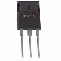
Package / Case
ISOPLUS247™
Vces, (v)
1700
Ic25, Tc=25°c, Igbt, (a)
38
Ic90, Tc=90°c, Igbt, (a)
20
Vce(sat), Max, Tj=25°c, Igbt, (v)
3.5
Tfi, Typ, Igbt, (ns)
250
Eoff, Typ, Tj=125°c, Igbt, (mj)
13.6
Rthjc, Max, Igbt, (°c/w)
0.65
If, Tc=90°c, Diode, (a)
14
Rthjc, Max, Diode, (k/w)
1.5
Package Style
ISOPLUS247
Lead Free Status / RoHS Status
Lead free / RoHS Compliant


High Voltage
IGBT with Diode
Symbol
BV
V
I
I
V
Electrically Isolated Tab
Symbol
V
V
V
V
I
I
I
I
SSOA
(RBSOA)
t
P
T
T
T
F
V
Maximum lead temperature for soldering
1.6 mm (0.062 in.) from case for 10 s
Weight
© 2004 IXYS All rights reserved
CM
CES
GES
C25
C90
F90
SC
C
JM
GE(th)
GEM
J
stg
CE(sat)
CES
CGR
GES
C
ISOL
CES
Test Conditions
I
I
V
V
V
I
Test Conditions
T
T
Continuous
Transient
T
T
T
V
Clamped inductive load
T
T
Mounting force with clamp
50/60 Hz, 1 minute
C
C
C
GE
J
J
C
C
C
GE
J
C
CE
CE
= 125°C, V
= 25°C to 150°C
= 25°C to 150°C; R
= 25°C
= 90°C
= 25°C, 1 ms
= 15 V, T
= 25°C
= 1mA, V
= 250 µA, V
= 0.8 • V
= 0 V
= 0 V, V
= I
C90
, V
GE
GE
VJ
CES
CE
GE
= 15 V
= ±20 V
= 125°C, R
= 1200 V; V
= 0 V
CE
= V
GE
GE
Note 1
= 1 MΩ
G
= 5Ω
GE
T
(T
J
= 15 V, R
= 125°C
J
IXGR 32N170AH1
= 25°C unless otherwise specified)
T
Advance Technical Information
J
= 125°C
G
= 10Ω
1700
min.
3.0
Characteristic Values
22...130/5...30
-55 ... +150
-55 ... +150
Maximum Ratings
@ 0.8 V
typ.
4.2
4.8
I
CM
1700
1700
2500
300
±20
±30
200
= 70
10
200
150
26
17
14
max.
CES
±100
5
500
5.0
5.2
8
N/lb
mA
µs
°C
µA
nA
°C
°C
°C
~V
W
V
V
V
V
V
V
V
V
A
A
A
A
A
g
V
I
V
t
ISOPLUS247 (IXGR)
G = Gate,
E = Emitter
Features
Applications
C25
fi(typ)
Electrically Isolated tab
High current handling capability
MOS Gate turn-on
- drive simplicity
Rugged NPT structure
Molding epoxies meet UL 94 V-0
flammability classification
Capacitor discharge & pulser circuits
AC motor speed control
DC servo and robot drives
DC choppers
Uninterruptible power supplies (UPS)
Switched-mode and resonant-mode
power supplies
CES
CE(sat)
E153432
G
C
E
= 1700
=
=
=
C = Collector,
5.2
ISOLATED TAB
26
50 ns
DS99233(11/04)
A
V
V
Related parts for IXGR32N170H1
Image
Part Number
Description
Manufacturer
Datasheet
Request
R


Part Number:
Description:
HiPerFET Power MOSFETs
Manufacturer:
IXYS Corporation
Datasheet:
Part Number:
Description:
J-K-Type Flip-Flop
Manufacturer:
IXYS Corporation
Datasheet:
Part Number:
Description:
HiPerRF Power MOSFETs
Manufacturer:
IXYS Corporation
Datasheet:
Part Number:
Description:
Rectifier Module for Three Phase Power Factor Correction
Manufacturer:
IXYS Corporation
Datasheet:
Part Number:
Description:
Thyristor Modules Thyristor/Diode Modules
Manufacturer:
IXYS Corporation
Datasheet:
Part Number:
Description:
Thyristor Modules Thyristor/Diode Modules
Manufacturer:
IXYS Corporation
Datasheet:
Part Number:
Description:
Thyristor Modules Thyristor/Diode Modules
Manufacturer:
IXYS Corporation
Datasheet:
Part Number:
Description:
Thyristor Modules Thyristor/Diode Modules
Manufacturer:
IXYS Corporation
Datasheet:
Part Number:
Description:
Thyristor Modules /Diode Modules
Manufacturer:
IXYS Corporation
Datasheet:
Part Number:
Description:
Thyristor Modules /Diode Modules
Manufacturer:
IXYS Corporation
Datasheet:
Part Number:
Description:
Thyristor Modules Thyristor/Diode Modules
Manufacturer:
IXYS Corporation
Datasheet:
IXGR32N170H1 Summary of contents
Page 1
... I = 250 µ GE(th 0.8 • V CES CE CES ± GES CE(sat) C C90 GE © 2004 IXYS All rights reserved Advance Technical Information IXGR 32N170AH1 Maximum Ratings 1700 = 1 MΩ 1700 GE ±20 ± 200 = 5Ω 0 10Ω 200 -55 ... +150 150 -55 ... +150 22...130/5...30 2500 300 ...
Page 2
... Switching times may increase for V increased See DH60-18A and IXGH32N170A datasheets for additional characteristics IXYS reserves the right to change limits, test conditions, and dimensions. IXYS MOSFETs and IGBTs are covered by 4,835,592 one or moreof the following U.S. patents: 4,850,072 4,881,106 Characteristic Values (T = 25° ...