J112RLRAG ON Semiconductor, J112RLRAG Datasheet - Page 3
J112RLRAG
Manufacturer Part Number
J112RLRAG
Description
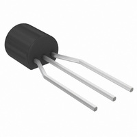
TRANS GP JFET N-CH 35V TO-92
Manufacturer
ON Semiconductor
Datasheet
1.J112G.pdf
(5 pages)
Specifications of J112RLRAG
Current - Drain (idss) @ Vds (vgs=0)
5mA @ 15V
Fet Type
N-Channel
Voltage - Breakdown (v(br)gss)
35V
Voltage - Cutoff (vgs Off) @ Id
1V @ 1µA
Resistance - Rds(on)
50 Ohm
Mounting Type
Through Hole
Package / Case
TO-92-3 (Standard Body), TO-226
Power - Max
350mW
Configuration
Single
Transistor Polarity
N-Channel
Gate-source Breakdown Voltage
35 V
Drain Current (idss At Vgs=0)
5 mA
Mounting Style
Through Hole
Breakdown Voltage Vbr
35V
Gate-source Cutoff Voltage Vgs(off) Max
-5V
Power Dissipation Pd
350mW
Operating Temperature Range
-65°C To +150°C
No. Of Pins
3
Leaded Process Compatible
Yes
Rohs Compliant
Yes
Lead Free Status / RoHS Status
Lead free / RoHS Compliant
Available stocks
Company
Part Number
Manufacturer
Quantity
Price

Company:
Part Number:
J112RLRAG()
Manufacturer:
MOT
Quantity:
2 059


PULSE WIDTH
DUTY CYCLE
1000
1000
500
200
100
500
200
100
5.0
2.0
1.0
5.0
2.0
1.0
50
20
10
50
20
10
0.5 0.7 1.0
0.5 0.7 1.0
R
50 W
V
GEN
INPUT PULSE
GEN
Figure 5. Switching Time Test Circuit
t
t
r
f
≤ 0.25 ns
≤ 0.5 ns
= 2.0 ms
≤ 2.0%
INPUT
R
Figure 1. Turn−On Delay Time
Figure 3. Turn−Off Delay Time
K
R
= R
K
= 0
R
50 W
2.0
D
2.0
R
K
′
SET V
K
I
I
D
= 0
R
D
, DRAIN CURRENT (mA)
GG
, DRAIN CURRENT (mA)
R
3.0
3.0
R D +
K
DS(off)
& R
= R
R
K
D
V
= 10 V
GG
′
R D ) R T ) 50
5.0 7.0 10
GG
5.0 7.0
R D (R T ) 50)
J111
J112
J113
J111
J112
J113
R
TYPICAL SWITCHING CHARACTERISTICS
+V
D
T
10
DD
J
= 25°C
T
50 W
J
= 25°C
R
V
V
T
GS(off)
GS(off)
20
20
= 7.0 V
= 5.0 V
OUTPUT
= 7.0 V
= 5.0 V
30
= 12 V
30
= 12 V
http://onsemi.com
J111, J112
50
50
The switching characteristics shown above were measured using a test
circuit similar to Figure 5. At the beginning of the switching interval,
the gate voltage is at Gate Supply Voltage (−V
Voltage (V
to the voltage divider. Thus Reverse Transfer Capacitance (C
Gate−Drain Capacitance (C
During the turn−on interval, Gate−Source Capacitance (C
discharges through the series combination of R
discharge to V
combination of effective load impedance (R′
Resistance (r
Predicting turn−on time is somewhat difficult as the channel resistance
r
approaches zero and r
turn−on time is non−linear. During turn−off, the situation is reversed
with r
The above switching curves show two impedance conditions; 1) R
is equal to R
stages where the driving source impedance is normally the load
impedance of the previous stage, and 2) R
driving source impedance is that of the generator.
3
ds
1000
1000
is a function of the gate−source voltage. While C
500
200
100
500
200
100
5.0
2.0
1.0
5.0
2.0
1.0
50
20
10
50
20
10
ds
0.5 0.7 1.0
0.5 0.7 1.0
increasing as C
DS
ds
D
) is slightly lower than Drain Supply Voltage (V
, which simulates the switching behavior of cascaded
). During the turn−off, this charge flow is reversed.
DS(on)
R
K
R
R
= 0
K
K
through R
ds
= R
= 0
R
2.0
2.0
gd
K
decreases. Since C
Figure 2. Rise Time
I
I
Figure 4. Fall Time
D
D
D
= R
charges.
′
, DRAIN CURRENT (mA)
, DRAIN CURRENT (mA)
gd
3.0
3.0
D
) is charged to V
′
NOTE 1
G
and R
5.0 7.0
5.0 7.0
J111
J112
J113
K
J111
J112
J113
K
in series with the parallel
gd
T
10
10
= 0 (low impedance) the
J
GG
= 25°C
discharges through r
GG
T
D
Gen
J
) and Drain−Source
). The Drain−Source
= 25°C
+ V
V
gs
and R
V
GS(off)
20
20
GS(off)
discharges, V
DS
.
= 7.0 V
= 5.0 V
K
= 12 V
30
30
= 7.0 V
= 5.0 V
= 12 V
. C
DD
gd
rss
50
50
) due
must
) or
gs
GS
ds
K
)
,
Related parts for J112RLRAG
Image
Part Number
Description
Manufacturer
Datasheet
Request
R

Part Number:
Description:
ON Semiconductor [VOLTAGE REGULATOR]
Manufacturer:
ON Semiconductor
Datasheet:
Part Number:
Description:
357-036-542-201 CARDEDGE 36POS DL .156 BLK LOPRO
Manufacturer:
ON Semiconductor
Datasheet:
Part Number:
Description:
357-036-542-201 CARDEDGE 36POS DL .156 BLK LOPRO
Manufacturer:
ON Semiconductor
Datasheet:
Part Number:
Description:
357-036-542-201 CARDEDGE 36POS DL .156 BLK LOPRO
Manufacturer:
ON Semiconductor
Datasheet:
Part Number:
Description:
357-036-542-201 CARDEDGE 36POS DL .156 BLK LOPRO
Manufacturer:
ON Semiconductor
Datasheet:
Part Number:
Description:
357-036-542-201 CARDEDGE 36POS DL .156 BLK LOPRO
Manufacturer:
ON Semiconductor
Datasheet:
Part Number:
Description:
357-036-542-201 CARDEDGE 36POS DL .156 BLK LOPRO
Manufacturer:
ON Semiconductor
Datasheet:
Part Number:
Description:
357-036-542-201 CARDEDGE 36POS DL .156 BLK LOPRO
Manufacturer:
ON Semiconductor
Datasheet:
Part Number:
Description:
357-036-542-201 CARDEDGE 36POS DL .156 BLK LOPRO
Manufacturer:
ON Semiconductor
Datasheet:
Part Number:
Description:
357-036-542-201 CARDEDGE 36POS DL .156 BLK LOPRO
Manufacturer:
ON Semiconductor
Datasheet:
Part Number:
Description:
357-036-542-201 CARDEDGE 36POS DL .156 BLK LOPRO
Manufacturer:
ON Semiconductor
Datasheet:
Part Number:
Description:
Manufacturer:
ON Semiconductor
Datasheet:
Part Number:
Description:
Manufacturer:
ON Semiconductor
Datasheet:
Part Number:
Description:
Manufacturer:
ON Semiconductor
Datasheet: