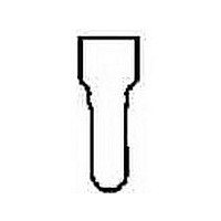
1-35115-0 TE Connectivity, 1-35115-0 Datasheet - Page 11

1-35115-0
Manufacturer Part Number
1-35115-0
Description
TERMINAL, CLOSED END SPLICE, CRIMP CLEAR
Manufacturer
TE Connectivity
Type
Splice Terminalr
Datasheet
1.1-35115-0.pdf
(16 pages)
Specifications of 1-35115-0
Wire Gauge
14-22
Body Plating
Tin
Body Material
Copper
Insulation
Insulated
Product Depth (mm)
8.71mm
Product Length (mm)
17.27mm
Color
Transparent
Connector Type
Closed End Splice
Insulator Color
Clear
Termination Method
Crimp
Wire Size (awg)
22-14
Contact Material
Copper
Contact Plating
Tin
Insulator Material
Nylon
Rohs Compliant
Yes
Product Type
Splice
Sealed
No
Splice Type
Closed End
Insulation Support
Non-Insulation Support
Finish
Tin
Wire/cable Size (cma)
509 – 5,180
Wire Range (mm [awg])
0.30-2.00² [22-14]
Opening Diameter [min.] (mm [in])
6.35 [0.250]
Government/industry Qualification
No
Rohs/elv Compliance
RoHS compliant, ELV compliant
Lead Free Solder Processes
Not relevant for lead free process
Rohs/elv Compliance History
Always was RoHS compliant
Marking
ECN
Packaging Method
Tape Mounted
Packaging Quantity
2,500
Lead Free Status / RoHS Status
Compliant
Available stocks
Company
Part Number
Manufacturer
Quantity
Price
Company:
Part Number:
1-35115-0
Manufacturer:
TE
Quantity:
20 000
*Partially closing hand tools to “oval”
Catalog 65472
Revised 04-04
www.tycoelectronics.com
NO. 22
NO. 20
NO. 18
NO. 16
NO. 14
NO. 12
NO. 10
splice permits use of solid wires in
these combinations.
WIRE
SIZE
TO BE SOLD
ONLY WITH
INSTALLATION
INSTRUCTIONS
LISTED
424 C
NO. OF
WIRES
1
2
3
4
5
6
7
8
9
1
2
3
1
2
3
1
2
1
2
1
1
NO. 22 NO. 20 NO. 18 NO. 16 NO. 14 NO. 12 NO. 10
CLOSED END SPLICE PRESSURE TYPE
Strip Length — 11.11 mm [.438 in.] Min.—
ULLISTED AND CSACERTIFIED WIRE
6-7
5-6
4-5
3-5
1-4
4-6
1-4
2-5
1-3
1-4
1-2
—
—
Circular Mil Range 5,180 — 13,100
7
6
5
4
3
2
1
6
SOL. OR STR. WIRE COMB. CHAR T
Use “18-10 VS or 12-10 ECV” Tooling
WIRE CONNECTORS— TYPE VS
WIRE SIZE 22-10 SOL. OR STR.
300 Volt Max.
Catalog No.34308 & 34865
NO. OF ADDITIONAL WIRES OF ONE WIRE SIZE
12.70 mm [.500 in.] Max.
Dimensions are in inches and
millimeters unless otherwise
specified. Values in brackets
are metric equivalents.
5-6
4-5
3-4
2-3
1-2
5-6
4-5
3-4
4-5
2-4
1-3
3-4
1-4
2-4
1-2
1-3
—
—
4
1
1
COMBINATIONS
3-5
3-4
2-3
2-3
3-4
2-4
2-3
3-5
2-4
1-3
2-3
1-3
1-3
1-2
1-3
—
—
1*
2
1
1
Closed End Splices
Vinyl Wire Combination Charts, For Splices on Page 2
INSTRUCTIONS: Use as shown
for OEM applications; otherwise,
for all field applications, twist wires
together before crimping. Mini-
mum loading is eight No. 22
90°C Max.
2-3
2-3
1-2
1-2
2-3
1-2
1-2
1-3
1-2
1-2
—
—
1*
2
1
1
2
2
1
1
1
1-2
1-2
1-2
—
—
1*
—
2
1
1
1
1
1
2
1
1
1
1
1
1
1
408-1397
Dimensions are shown for
reference purposes only.
Specifications subject
to change.
—
—
—
—
—
1*
—
—
—
1
1
1
1
1
1
1
1
1
1
1
1
CERTIFIED
LR 7189
CU
—
—
—
—
—
—
—
—
—
—
—
—
—
—
—
1*
1*
1
1
1
1
INSTRUCTIONS: Use as shown for OEM applications; otherwise, for all field
applications, twist wires together before crimping. Minimum loading is five
No. 22 wires.
NO. 22
NO. 20
NO. 18
NO. 16
NO. 14
NO. 12
WIRE
SIZE
TO BE SOLD
ONLY WITH
INSTALLATION
INSTRUCTIONS
LISTED
105°C
424 C
MAX.
USA: 1-800-522-6752
Canada: 1-905-470-4425
Mexico: 01-800-733-8926
C. America: 52-55-5-729-0425
NO. OF
WIRES
10
11
1
2
3
4
5
6
7
8
9
1
2
3
4
1
2
3
4
1
2
3
1
2
1
CLOSED END SPLICE PRESSURE TYPE
Strip Length— 10.72 mm [.422 in.] Min.—
ULLISTED AND CSACERTIFIED WIRE
NO. 22
Circular Mil Range 3,248 — 11,400
4-13
3-12
1-10
3-10
1-10
2-11
4-11
WIRE CONNECTORS— TYPE ECV
1-9
1-8
1-7
1-6
1-5
1-4
1-3
2-9
1-8
1-7
1-9
1-8
1-7
1-9
1-6
1-5
1-4
1-6
STRANDED WIRE COMB. CHART
Catalog No.329251 & 53234-1
1000 Volt Max. Fixtures & Signs
600 Volt Max. Building Wiring
NO. OF ADDITIONAL WIRES OF ONE WIRE SIZE
11.51 mm [.453 in.] Max.
WIRE SIZE 22-12 STR.
Use “18-10 EC” Tooling
COMBINATIONS
NO. 20
3-9
2-8
1-7
1-6
1-6
1-5
1-5
1-4
1-3
1-3
1-2
3-9
2-8
1-7
1-6
2-8
1-7
1-5
1-4
1-7
1-5
1-3
1-7
1-3
1-4
NO. 18
2-6
2-5
1-5
1-4
1-4
1-4
1-3
1-2
1-2
1-2
2-6
1-5
1-4
1-4
1-6
1-5
1-4
1-3
1-5
1-3
1-2
1-4
1-3
1
1
South America: 55-11-3611-1514
Hong Kong: 852-2735-1628
Japan: 81-44-844-8013
UK:44-141-810-8967
(Continued)
NO. 16
1-4
1-3
1-3
1-3
1-3
1-2
1-2
1-2
1-4
1-3
1-2
1-2
1-3
1-3
1-2
1-3
1-2
1-2
—
1
1
1
1
1
1
NO. 14
408-1479
1-2
1-2
1-2
1-2
1-2
1-2
1-2
1-2
1-2
—
—
—
1
1
1
1
1
1
1
1
1
1
1
1
1
CERTIFIED
LR 7189
MAX.
90°C
NO. 12
—
—
—
—
—
—
—
—
—
1
1
1
1
1
1
1
1
1
1
1
1
1
1
1
1
11


