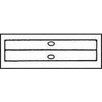
8-34323-3 TE Connectivity, 8-34323-3 Datasheet - Page 50

8-34323-3
Manufacturer Part Number
8-34323-3
Description
TERMINAL, BUTT SPLICE
Manufacturer
TE Connectivity
Type
Splice Terminalr
Series
Solistrandr
Datasheet
1.8-34323-3.pdf
(60 pages)
Specifications of 8-34323-3
Wire Gauge
4
Body Plating
Tin
Body Material
Copper
Insulation
Non-Insulated
Product Depth (mm)
11.76mm
Product Length (mm)
28.96mm
Color
Not Required
Connector Type
Butt Splice
Wire Size (awg)
4
Contact Material
Copper
Contact Plating
Tin
Insulator Material
Non-Insulated
Leaded Process Compatible
Yes
Rohs Compliant
Yes
Product Type
Splice
Sealed
No
Splice Type
Butt
Body Style
SOLISTRAND
Insulation Support
Non-Insulation Support
Finish
Tin
Inside Diameter (mm [in])
7.52 [0.296]
Wire/cable Size (cma)
33,100 – 52,600
Butt Splice Type
Standard
Wire Range (mm [awg])
21.00² [4]
Stock Thickness (mm [in])
1.85 [0.073]
Nominal Outside Diameter (mm [in])
11.76 [0.463]
Government/industry Qualification
No
Rohs/elv Compliance
RoHS compliant, ELV compliant
Lead Free Solder Processes
Not relevant for lead free process
Rohs/elv Compliance History
Always was RoHS compliant
Packaging Method
Loose Piece
Packaging Quantity
25/Box
Lead Free Status / RoHS Status
Compliant
50
UL 486 C Wire Size
AWG 22 to 6
UL 486 A Wire Size
AWG 4 to 600 MCM
Test Sequences
Test Group 1
Mechanical Sequence
1. Secureness
2. Pullout
Test Group 2
Mechanical Sequence
1. Secureness
2. Static Heat
3. Pullout
Note: Testing conducted on non-plated
copper wire with UL approved insulation.
SOLISTRAND, Budget and DIAMOND GRIP
Uninsulated Terminals and Splices
Description of UL 486A & C Test Procedures and Requirements
for Butt and Parallel Type Splices
For drawings, technical data or samples, contact your AMP sales engineer or call the AMP Technical Support Center 1-800-522-6752.
Dimensions are in inches and millimeters unless otherwise specified. Values in brackets are metric equivalents.
Specifications subject to change. Consult AMP for latest specifications.
Pullout Test Requirements
Splices must not be separate from wire when
subjected to the listed load for one minute.
Wire Size
AWG
250
300
350
400
500
600
1/0
2/0
3/0
4/0
22
20
18
16
14
12
10
8
6
4
2
Force (lbs.)
Pullout
140
180
250
300
350
450
500
550
600
650
800
900
10
10
15
25
35
40
45
50
8
Secureness Test Requirements
Note: Test Duration=30 Minutes
Wire Size
18-16
12-10
AWG
14
8
6
4
Requirement:
Connector temperatures must not exceed the ambi-
ent temperature plus 50°C [90°F] after stability is
attained.
Stability:
A test sample is considered to have attained a stable
temperature when three readings taken at not less
than 10 minute intervals show no more than a 2°C
[3.6°F] variation between any two readings.
Static Heat Test Requirements
Wire Size
AWG
250
300
350
400
500
600
1/0
2/0
3/0
4/0
22
20
18
16
14
12
10
8
6
4
2
Bushing
Dia.
1/4
3/8
3/8
3/8
1/2
1/2
Height
10 1/4
11 3/4
11 3/4
11
11
11
Catalog 65505
Test Current
(Amperes)
Revised 9-00
125
170
230
265
310
360
405
445
505
545
620
690
12
17
18
30
35
50
70
95
Weight
9
(lbs.)
18
30
2
3
5
8


