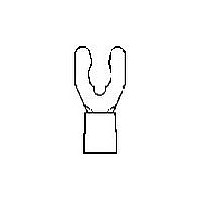
53000-1 TE Connectivity, 53000-1 Datasheet - Page 56

53000-1
Manufacturer Part Number
53000-1
Description
Manufacturer
TE Connectivity
Type
Ring Tongue Terminalr
Datasheet
1.53000-1.pdf
(60 pages)
Specifications of 53000-1
Stud Size
2mm
Wire Gauge
22-26
Body Plating
Tin
Body Material
Phosphor Bronze
Insulation
Non-Insulated
Operating Temp Range
-55C to 135C
Color
Yellow
Terminal Shape
Spring Spade, Short
Receptacle Style
Straight
Body Style
Budget
Barrel Type
Closed Barrel
Wire/cable Type
Regular Wire
Insulation Support
Non-Insulation Support
Stud Diameter (mm [in])
2.18 [0.086]
Shape
SPADE-030
Heavy Duty
No
Finish
Tin
Wire/cable Size (cma)
202 – 810
Wire Range (mm [awg])
0.12-0.40² [26-22]
Barrel I.d. Min. (mm [in])
0.86 [0.034]
Stock Thickness (mm [in])
0.51 [0.020]
Government/industry Qualification
No
Rohs/elv Compliance
RoHS compliant, ELV compliant
Lead Free Solder Processes
Not reviewed for lead free solder process
Rohs/elv Compliance History
Always was RoHS compliant
Packaging Method
Loose Piece
Lead Free Status / RoHS Status
Compliant
56
DYNA-CRIMP II
Battery Operated
Hydraulic Power Unit
AMP application tools are designed to
produce a carefully controlled uniform
pressure crimp, regardless of how they
are powered. All tools shown are
specially designed for AMP products
and are precision machined from hard
tool steel.
Part No. 122271-1
4
SOLISTRAND, Budget and DIAMOND GRIP
Uninsulated Terminals and Splices
Application Tooling
Power Units Accessories
1
2
3
4
Note: All Hoses and Handle Control Assemblies have a 3⁄8" high flow male coupler (311470-1) on each end.
For additional tooling information, call 1-800-722-1111.
For drawings, technical data or samples, contact your AMP sales engineer or call the AMP Technical Support Center 1-800-522-6752.
Dimensions are in inches and millimeters unless otherwise specified. Values in brackets are metric equivalents.
Specifications subject to change. Consult AMP for latest specifications.
Contact AMP Incorporated for usage recommendations.
Also see AMP Customer Manual 409-5860.
Also see AMP Customer Manual 409-1950.
Also see AMP Customer Manual 409-5869.
Power Unit No.
For Use With
369120-1
369120-2
314979-1
122271-1
All Power Units and Heads have a 3⁄8" high flow female coupler (311471-1).
69120-1
69120-2
Hand Operated Power Unit
314979-1
Refer to the table below for accessories.
Control
Handle
3
3
3
3
2
4
2
15' Hose Assembly (1/4” I.D.)
(Hose, head and dies not included)
15' Handle Control Assembly—Hose & Cord
21' Handle Control Assembly—Hose & Cord
28' Handle Control Assembly—Hose & Cord
2' Hose Assembly (1/4” I.D.)
3' Hose Assembly (1/4” I.D.)
7' Hose Assembly (1/4” I.D.)
7' Handle Control Assembly—Hose & Cord
3-Way Multi-Directional Value
3-Way Multi-Directional Value (Elec.Ctl)
15' Foot Switch Assembly
Typical interchangable hose,
head and dies not included
15' Hose Assembly
21' Hose Assembly
(Continued)
Accessory Description
3' Hose Assembly
7' Hose Assembly
Assembly
Hose
Control
Accessory
Foot
1-59907-5
2-59907-1
2-59907-8
1-59909-5
2-59909-1
DYNA-CRIMP Electric
Hydraulic Power Unit
Power Unit Only
(Includes Pressure Release)
115 Volts (60 Hz) — 69120-1
230 Volts (60 Hz) — 69120-2
314990-1
314990-2
314990-3
314990-4
Part No.
59907-7
68284-1
59909-3
59909-7
59220
59220-2
1
1
Need Hose Assembly
68284-1 Foot Switch
Assembly needed with
these Hose Assemblies
and 69120
More Flexible, Lighter Weight.
Recommended for use with
DYNA-CRIMP II Battery
Operated Hydraulic Power Un i t
For use with
Foot Switch only
Multidirectional
Remarks
Catalog 65505
Valve
3
3
Revised 9-00


