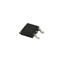
ZXMP10A17KTC Diodes Zetex, ZXMP10A17KTC Datasheet - Page 35

ZXMP10A17KTC
Manufacturer Part Number
ZXMP10A17KTC
Description
MOSFET P-CH 100V DPAK
Manufacturer
Diodes Zetex
Datasheet
1.BAT1000TA.pdf
(96 pages)
Specifications of ZXMP10A17KTC
Fet Type
MOSFET P-Channel, Metal Oxide
Fet Feature
Standard
Rds On (max) @ Id, Vgs
350 mOhm @ 1.4A, 10V
Drain To Source Voltage (vdss)
100V
Current - Continuous Drain (id) @ 25° C
2.4A
Vgs(th) (max) @ Id
4V @ 250µA
Gate Charge (qg) @ Vgs
10.7nC @ 10V
Input Capacitance (ciss) @ Vds
424pF @ 50V
Power - Max
2W
Mounting Type
Surface Mount
Package / Case
DPak, TO-252 (2 leads+tab), SC-63
Lead Free Status / RoHS Status
Lead free / RoHS Compliant
Other names
ZXMP10A17KTR
P
P
+V
0V
If the MOSFET is required to switch
at 1MHz from a 5V drive the power
dissipation in each driver transistor can
be estimated as:
D(npn)
D(pnp)
With both devices dissipating just
256mW, small surface mount bipolar
transistors are ideal, preferably
co-packaged as complementary dual
devices.
Application example 3:
Resonant converter for
CCFL backlight applications
The backlight module of an LCD
display requires high efficiency
operation and is sensitive to cost.
There are two basic circuit topologies
for driving the CCFL lamps:
a) Resonant converter, using a bipolar
b) IC controller plus MOSFET
Resonant converter circuits are
cheaper than IC controller/ MOSFET
solutions and, with careful optimization,
efficiencies of greater than 90% can
be achieved. A simplified circuit is
shown in Figure 4:
Figure 4. Resonant converter
for LCD backlight
Characteristic
LCD Backlight
‘On’ resistance
Blocking voltage
Pulse current
Drive voltage
Temperature stability
Drive power
Speed
ESD sensitivity
Price per area of silicon
transistor half-bridge, or
half-bridge.
= (( V
= (V
G
DRIVE
/2 x Q x f) + (V
Q2
– (V
G
Bipolar transistor
Excellent - down to half that of the best MOSFET,
depending on drive current available.
Bi-directional blocking capability. BV
BV
High
Less than 1V
Excellent:
V
R
Moderate
Linear switch: very fast
Saturated switch: moderate
Very rugged
Comparable
/2)) x Q x f) + (V
CCFL
BE
CE(sat)
CBO
: approx. 2mV per °C
BE
may be appropriate for some applications.
x I
approx. 0.4% per °C
B
x t x f)
Q1
BE
The important power switch
selection characteristics are
voltage rating, on-state
resistance, gain and cost.
The circuit makes use of the
reverse BV
allows the use of the BV
characteristic, thus allowing
a lower BV
lower on-state resistance than its
MOSFET equivalent.
Application example 4:
DC brushless motor driving
Brushless DC motors are popular due
to their high efficiency, high torque,
longer operating life, reduced noise and
lower EMI.
Commutation is effected by switching
the current in the windings of the stator
in the required sequence to produce a
rotating magnetic field synchronous
with the rotor. Single phase, 2-phase or
3-phase motors, require respectively 1,
2 or 3 stator windings. Speed control
is usually achieved by PWM.
In 2-phase circuits each winding is
energized for half of the time and is
switched by a single drive transistor.
In single-phase bridge circuits (Figure 5)
the winding current is synchronously
commutated by switching diagonal
pairs of transistors, therefore the single
winding results in a cheaper, lighter
motor but the drive circuitry is more
complex.
In 3-phase bridge circuits a third leg is
added to the bridge which means that
both motor and drive costs are higher.
x I
B
x t x f)
CEO
EBO
rating and
rated device with a
CES
, BV
35
CEV
CEV
or
, or BV
+ Supply
- Supply
MOSFET
Good at full enhancement
Moderate at low gate drive
Mono-directional, may require a series Schottky diode
or back-to-back MOSFET pair in some applications.
Moderate
1.8V to 10V, depending on the optimization
R
High frequency: moderate
Fast
Sensitive
Comparable
DS(on)
CES
C1
approx. 0.6% per °C
D1
1N4148
ThRef
C
SPD
S
C
PWM
V
H+
MIN
LCK
H-
Common to all circuit types, the
requirements of the switch are to be
directly driven by the control circuit; to
minimize the voltage drop in the power
switch in order to maximize rotor speed
and circuit efficiency; to survive stall
currents and inductive transients during
switching.
In low voltage, low current applications
e.g. PC fans, where IC motor
controllers are required to operate on
3V rails, there are opportunities to
make effective use of a bipolar
transistor’s high current gain hold-up
and low V
where MOSFETs struggle to be cost
effective. The fan motor circuit in
Figure 5 is a hybrid bridge circuit where
PNP bipolar transistors are used for the
high side pair, and N-Channel MOSFETs
are used for the low side PWM driven
pair. This combination takes advantage
of the PNP transistor’s low R
which helps achieve high rotor speed.
To read this article in full, go to
www.zetex.com/thinkbipolar
CC
Figure 5.
Single-phase fan motor circuit
ZXBM1004
CE(sat)
V+ OP
Ph1Lo
Ph2Lo
Ph2Hi
Ph1Hi
FG
RD
Gnd
1N4004
D2
at low drive voltages
R5
R1
R2
R3
R6
Q1
Q3
CE(sat)
D3
W1
D4
Q4
Q2
R4
1.0


