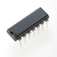
NJM2211M-TE1 NJR, NJM2211M-TE1 Datasheet

NJM2211M-TE1
Specifications of NJM2211M-TE1
Available stocks
Related parts for NJM2211M-TE1
NJM2211M-TE1 Summary of contents
Page 1
... Bipolar Technology ■ APPLICATIONS ● FSK demodulation ● Data synchronization ● Tone decoding ● FM detection ● Carrier detection ■ PIN CONFIGURATION Ver.2003-12-09 (4.5V to 20V) (0.01Hz to 300kHz) (2mV rms (±1% to ±80%) (20ppm / °C typical) DIP14, DMP14 ■ PACKAGE OUTLINE NJM2211D NJM2211M NJM2211D NJM2211M - 1 - ...
Page 2
BLOCK DIAGRAM ■ ABSOLUTE MAXIMUM RATINGS PARAMETER Supply Voltage Input Signal Level Power Dissipation Operating Temperature Range Storage Temperature Range - 2 - SYMBOL RATINGS + (DIP14) 700 D (DMP14) 300 T -40 ...
Page 3
ELECTRICAL CHARACTERISTICS PARAMETER Operating Voltage Operating Current Oscillator Frequency Accuracy Frequency Stability Temp. Coefficient Power Supply Rejection Upper Frequency Limit Lowest Operating Frequency Timing Resistor Timing Resistor Loop Phase Detector Peak Output Current Output Offset Current Output Impedance Maximum ...
Page 4
EQUIVALENT CIRCUIT ■ CIRCUIT FUNCTION ● Signal Input (Pin 2) The input signal is AC coupled to this terminal. The internal impedance at pin 2 is 20kΩ, Recommended input signal leveles in the range of 10mVrms to 3Vrms. ● ...
Page 5
Reference Voltage V (Pin 10) R This pin is internally biased at the reference voltage level internal reference for the voltage levels at pin 3, 8, 11, and 12. Pin 10 must be bypassed to ground with ...
Page 6
DESIGN EQUATIONS See Figure 1 for Definitions of Components. 1. VCO Center Frequency Internal Reference Voltage + ...
Page 7
APPLICATIONS FSK Decoding Figure 2 shows the basic circuit connection for FSK decoding. With reference to Figures 1 and 2, the functions of external components are defined as follows : R0 and C0 set the PLL center frequency. R1 ...
Page 8
Design Example 75 Band FSK demodulator with mark / space frequencies of 1110 / 1170Hz : Step 1 : Calculate =(1110+1170 2)=1140Hz 0 Step 2 : Choose R0=20kΩ (18kΩ fixed resistor in series with ...
Page 9
Design Instructions The circuit of Figure 4 can be optimized for any tone-detection application by the choice of five key circuit components : R0, R1, C0, C1, and C 1. Chose the range of 15kΩ to ...
Page 10
TYPICAL CHARACTERISTICS Operating Current Center Frequency Drift Center Frequency - 10 - VCO Frequency VCO Frequency [CAUTION] The specifications on this databook are only given for information , without any guarantee as regards either mistakes or omissions. The application ...


