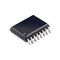
SI2400-KSR Silicon Laboratories Inc, SI2400-KSR Datasheet - Page 84

SI2400-KSR
Manufacturer Part Number
SI2400-KSR
Description
Telecom Line Management ICs 2400b/s System Side
Manufacturer
Silicon Laboratories Inc
Type
Integrated Global DAAr
Datasheet
1.SI2400-BS.pdf
(94 pages)
Specifications of SI2400-KSR
Product
Modem Chip
Supply Voltage (min)
3 V
Supply Current
21 mA
Maximum Operating Temperature
+ 85 C
Minimum Operating Temperature
- 40 C
Mounting Style
SMD/SMT
Package / Case
SOIC-16
Lead Free Status / RoHS Status
Lead free / RoHS Compliant
Available stocks
Company
Part Number
Manufacturer
Quantity
Price
Part Number:
SI2400-KSR
Manufacturer:
SI
Quantity:
20 000
Si2400
A
Introduction
Appendix B outlines the steps required to configure the
Si2400 for modem operation under typical examples.
The ISOmodem has been designed to be both easy to
use and flexible. The Si2400 has many features and
modes, which add to the complexity of the device, but
are not required for a typical modem configuration. The
goal of this appendix is to help the user to quickly make
a modem connection and begin evaluation of the
Si2400 under various operational examples.
Example 1: V.22bis in FCC countries
1. Power on reset
2. Set Host UART to 2400 bps
3. ATS07=06 set for QAM 2400 bps
4. ATDT18005551212<CR>
5. Next byte after “c” or “d” is modem data!
Example 2: V.22 in CTR21 countries
1. Power on reset
2. Set Host UART to 2400 bps with CTS flow control
3. ATS07=02 (set for DPSK 1200 bps)
4. ATSF5=1C (set DAA for CTR21)
5. ATSF7=18 (set DAA for CTR21)
6. ATDT18005551212<CR>
7. Next byte after “c” is modem data!
Example 3: Bell 103 in Australia
1. Power on reset
2. Set Host UART to 2400 bps with CTS flow control
3. ATS07=01 (set for FSK 300 bps)
4. ATSF5=38 (set DAA for Australia)
5. ATDT18005551212<CR>
84
PPENDIX
Si2400 may echo the following:
t – tone dial detected
, – dialing complete
r – ringback
b – busy tone
N – No carrier
c – connect
d – connect at 1200bps
Si2400 may echo the following:
t – tone dial detected
, – dialing complete
r – ringback
b – busy tone
N – No carrier
c – connect
B—
T
YPICAL
M
ODEM
A
PPLICATIONS
Rev. 1.3
6. Next byte after “c” is modem data!
Example 4: Bell 103 in Australia with
Parallel Phone Detect
1. Power on reset
2. Set Host UART to 2400 bps with CTS flow control
3. ATS07=01 (set for FSK 300 bps)
4. ATSF5=38 (set DAA for Australia)
5. ATSE2=C0 (enable ALERT pin)
6. ATDT18005551212<CR>
7. Next byte after “c” is modem data!
Example 5: Bell 212A in South Korea with
Japanese caller ID
1. Power on reset
2. Set Host UART to 2400 bps with CTS flow control
3. ATS07=00 (set for DPSK 1200 bps)
4. ATSF5=06(set DAA for South Korea)
5. ATS13=80 (set caller ID to Japanese format)
6. ATDT18005551212<CR>
7. Next byte after “c” is modem data!
Si2400 may echo the following:
t – tone dial detected
, – dialing complete
r – ringback
b – busy tone
N – No carrier
c – connect
Si2400 may echo the following:
t – tone dial detected
, – dialing complete
r – ringback
b – busy tone
N – No carrier
c – connect
When caller ID data is detected, Si2400 will echo “f”
indicating the line reversal, “m” indicating the mark, and
then caller ID data will follow.
-Si2400 may echo:
t – tone dial detected
, – dialing complete
r – ringback
b – busy tone
N – No carrier
c – connect
E
XAMPLES


