AC422AT OPTO 22, AC422AT Datasheet - Page 4
AC422AT
Manufacturer Part Number
AC422AT
Description
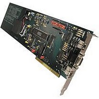
Computers, Interface Cards
Manufacturer
OPTO 22
Datasheet
1.AC422AT.pdf
(7 pages)
Specifications of AC422AT
Peak Reflow Compatible (260 C)
No
Leaded Process Compatible
No
Features
Serial Port RS-422/485, Nonisolated
Lead Free Status / RoHS Status
Contains lead / RoHS non-compliant


DATA SHEET
Form 473-010131
Opto 22 • 43044 Business Park Drive • Temecula, CA 92590-3614 • Phone: (951) 695-3000 • (800) 321-OPTO • Fax: (951) 695-3095 • www.opto22.com
Jumper Installation (cont.)
COMMUNICATION JUMPERS
and receiver (from Optomux), respectively. In a normal OPTOMUX network these jumpers should both be installed.
In a normal network these jumpers should both be installed.
Note: If multiple host computers are used, jumpers B2, B4, C2, and C4 should only be installed on the adapter card which is physically at the end of the serial network
cable.
installed, the enabling is under the control of the RTS output on the UART. When the RTS is active, the driver will be enabled. When RTS
is inactive, the driver is disabled.
the inactive state.
pull the receive (from OPTOMUX) to the inactive state. Also, C5 and C6 must be installed to passively pull the CTS to the inactive state.
from the RS-422/485 connection. Jumpers B7 and C7 should never be installed at the same time.
revision adapter cards which do not hae a CTS jumper, the RTS outputs must be looped back to the CTS inputs. This is done by connecting
the RTS positive (+) pin to the CTS positive (+) pin, and the RTS negative (-) pin to the CTS negative (-) pin using a suitable jumper wire
soldered on the 9-pin connector on the adapter end of the cable.
mode. A jumper installed sets the card into 2-wire mode.
Installing jumpers B2 and B4 connects 220 ohm terminating resistors from positive (+) to negative (-) on the transmitter (to Optomux)
Installing jumpers C2 and C4 connects 200 ohm terminating resistors for positive (+) to negative (-) on the RTS and CTS, respectively.
Jumper B7 controls the enabling of the RS-422/485 driver. With the jumper removed, the driver is always enabled. With the jumper
If jumper B7 is installed, jumpers B1 and B3 must also be installed. These jumpers passively pull the transmit lines (to OPTOMUX) to
If the adapter card is operating with a multidrop OPTOMUX network, jumpers B5 and B6 must be installed. These jumpers passively
Jumper C7 controls the enabling of the RS-422/485 driver. With the jumper installed, the enabling is under the control of the CTS input
The CTS jumper should always be installed on the adapter card when the RTS/CTS handshake lines are NOT being used. With earlier
The 2-wire jumper switches the card from 4-wire to 2-wire mode. A jumper out, which is the factory default, sets the card into 4-wire
Inside Sales: (800) 321-OPTO • Product Support: (800) TEK-OPTO • (951) 695-3080 • Fax: (951) 695-3017 • E-mail: sales@opto22.com
INTERFACES
PC ADAPTER CARDS
TRADITIONAL
page 4/6
Related parts for AC422AT
Image
Part Number
Description
Manufacturer
Datasheet
Request
R

Part Number:
Description:
SSR, PANEL MOUNT, 280VAC, 32VDC, 10A
Manufacturer:
OPTO 22
Datasheet:

Part Number:
Description:
SSR, PANEL MOUNT, 280VAC, 32VDC, 25A
Manufacturer:
OPTO 22
Datasheet:
Part Number:
Description:
SSR, PANEL MOUNT, 280VAC, 32VDC, 25A
Manufacturer:
OPTO 22
Datasheet:
Part Number:
Description:
SSR, PANEL MOUNT, 280VAC, 32VDC, 45A
Manufacturer:
OPTO 22
Datasheet:
Part Number:
Description:
SSR, PANEL MOUNT, 280VAC, 32VDC, 45A
Manufacturer:
OPTO 22
Datasheet:

Part Number:
Description:
SSR, 10A, 240VAC
Manufacturer:
OPTO 22
Datasheet:

Part Number:
Description:
Programmable Logic Controller
Manufacturer:
OPTO 22
Datasheet:

Part Number:
Description:
Programmable Logic Controller
Manufacturer:
OPTO 22
Datasheet:

Part Number:
Description:
Solid State Relays, Accessories
Manufacturer:
OPTO 22
Datasheet:
