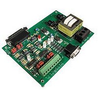
AC40B OPTO 22, AC40B Datasheet - Page 10

AC40B
Manufacturer Part Number
AC40B
Description
Computers, Interface Cards
Manufacturer
OPTO 22
Datasheet
1.AC40A.pdf
(15 pages)
Specifications of AC40B
Peak Reflow Compatible (260 C)
No
Leaded Process Compatible
No
Features
Fiber Optic Repeater, 240VAC
Lead Free Status / RoHS Status
Lead free / RoHS Compliant
DATA SHEET
Form 521-070823
Opto 22 • 43044 Business Park Drive • Temecula, CA 92590-3614 • Phone: (951) 695-3000 • (800) 321-OPTO • Fax: (951) 695-3095 • www.opto22.com
JUMPERING
inserted to configure the AC40 RS-485 port. Jumpers A1 - A6 select various possibilities for biasing and termination of the RS-485 link.
Jumpers A7 and A8 are used to select 2-wire or 4-wire mode.
2-wire Terminated/Not Biased
2-wire Unterminated
2-wire Terminated/Biased
4-wire Unterminated
4-wire Terminated/Biased
4-wire Terminated/Not Biased
A group of 8 jumpers labeled A1 - A8 is located on the left-hand side of the upper printed circuit board on the AC40. The jumpers are
When you configure your AC40 RS-485 communications link, keep these facts in mind:
1) RS-485 requires termination at both ends of the communications wiring.
2) The link must be biased in one place only.
3) Opto 22 remote Bricks have no bias or termination options.
4) The G4TERMR terminator does not have bias options.
5) When G4LC32 RS-485 serial ports are terminated, they are automatically biased.
6) Biasing is usually done at the “HOST” end.
Inside Sales: (800) 321-OPTO • Product Support: (800)TEK-OPTO • (951) 695-3080 • Fax: (951) 695-3017 • E-mail: sales@opto22.com
Mode
(AC40 is shipped with these
No Jumpers
A2, A7, A8
A7, A8
A1, A2, A3, A7, A8
jumpers installed.)
A1, A2, A3, A4, A5, A6
A2, A5
Install Jumpers
INTERFACES
TRADITIONAL
STAND ALONE
page 10/14


