AC7 OPTO 22, AC7 Datasheet - Page 8
AC7
Manufacturer Part Number
AC7
Description
Computers, Interface Cards
Manufacturer
OPTO 22
Specifications of AC7
Peak Reflow Compatible (260 C)
No
Leaded Process Compatible
No
Features
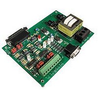
RS232 To RS422 Converter
Interface
RS-422⁄485
Module Type
Adapter Card
Mounting Type
Protective Enclosure
Voltage, Supply
115 VAC ± 10 VAC @ 50⁄60 Hz
Lead Free Status / RoHS Status
Contains lead / RoHS non-compliant
Available stocks
Company
Part Number
Manufacturer
Quantity
Price

Part Number:
AC713
Manufacturer:
ALPHA
Quantity:
20 000
Part Number:
AC7201-50JC
Manufacturer:
AMD
Quantity:
20 000
Part Number:
AC744
Manufacturer:
SKYWORKS/思佳讯
Quantity:
20 000
Company:
Part Number:
AC76951
Manufacturer:
ALPHA
Quantity:
5 510
Part Number:
AC7C4096B012TCN
Manufacturer:
ALLIANCE
Quantity:
20 000


INSTALLATION
CONNECTING AC POWER TO THE AC7A/B
8 AC7A/B User’s Guide
Caution: Make sure that power is OFF while making or removing all connections to the AC7A/B and Optomux.
For safety purposes, a plastic insulating cover is provided for the power terminal block, and shouldbe installed after
power wiring is completed.
The AC7A/B has a terminal strip with three screw terminals for AC power. The AC power, which is supplied to the
AC7A/B, should have three wires, two for AC power and one for earth ground (usually colored green). Connect the
wire for earth ground (usually colored green) to the center screw terminal which is labeled GND. Connect theother
two wires to the terminals marked AC, one wire per terminal. The polarity of the AC power wires withrespect to the
AC screw terminals on the power connector of the AC7A/B does not matter.
If using a standard, 3-conductor power cord with a three-pronged plug, it should be at least #18 gauge wires or
larger. On one end should be the three-pronged plug; the other should have three wires with approximately
1/4” (6mm) of insulation stripped off the end of each wire. Find the wire that corresponds to earth ground
(usuallycolored green) and connect this to the terminal labeled GND. You may determine the ground wire by using
an ohmmeterand testing for continuity with the ground pin on the plug. The other two wires should be connected
tothe terminals marked AC, one wire per terminal. The polarity of the AC power wires with respect to the screw
terminals marked AC on the AC7A/B does not matter.
Figure 2-1: AC7A/B Card Dimensions
Figure 2-2: Connector Terminal
Related parts for AC7
Image
Part Number
Description
Manufacturer
Datasheet
Request
R

Part Number:
Description:
Standard AC Input Module, 180 To 280 VAC Input Voltage Range, Voltage Input, 15 MA Output Current, 12 To 18 VDC Output Voltage, General
Manufacturer:
OPTO 22
Datasheet:

Part Number:
Description:
AC Output Module
Manufacturer:
OPTO 22
Datasheet:

Part Number:
Description:
SSR, PANEL MOUNT, 280VAC, 32VDC, 10A
Manufacturer:
OPTO 22
Datasheet:

Part Number:
Description:
SSR, PANEL MOUNT, 280VAC, 32VDC, 25A
Manufacturer:
OPTO 22
Datasheet:
Part Number:
Description:
SSR, PANEL MOUNT, 280VAC, 32VDC, 25A
Manufacturer:
OPTO 22
Datasheet:
Part Number:
Description:
SSR, PANEL MOUNT, 280VAC, 32VDC, 45A
Manufacturer:
OPTO 22
Datasheet:
Part Number:
Description:
SSR, PANEL MOUNT, 280VAC, 32VDC, 45A
Manufacturer:
OPTO 22
Datasheet:

Part Number:
Description:
Solid State Relays, Accessories
Manufacturer:
OPTO 22
Datasheet:
