AC8 OPTO 22, AC8 Datasheet - Page 8
AC8
Manufacturer Part Number
AC8
Description
Computers, Interface Cards
Manufacturer
OPTO 22
Datasheet
1.AC8.pdf
(11 pages)
Specifications of AC8
Peak Reflow Compatible (260 C)
No
Leaded Process Compatible
No
Features
Half Duplex Modem Interface, 5VDC
Lead Free Status / RoHS Status
Lead free / RoHS Compliant
Available stocks
Company
Part Number
Manufacturer
Quantity
Price

Part Number:
AC80566 400SLGMB
Manufacturer:
INTEL
Quantity:
20 000
Part Number:
AC80566 533 SLGPT
Manufacturer:
INTEL
Quantity:
20 000
Company:
Part Number:
AC80566-533
Manufacturer:
MITSUMI
Quantity:
1 357
Part Number:
AC80566-533
Manufacturer:
INTEL
Quantity:
20 000
Company:
Part Number:
AC80566-533/SLB6P
Manufacturer:
UTC
Quantity:
301
Part Number:
AC80566UC005DE S LB2C
Manufacturer:
INTEL
Quantity:
20 000
Part Number:
AC80566UC005DE-SLB2C
Manufacturer:
INTEL
Quantity:
20 000
Company:
Part Number:
AC80566UC005DESLB2C
Manufacturer:
INTEL
Quantity:
528
Company:
Part Number:
AC80566UE025DH/QBYM
Manufacturer:
INTEL
Quantity:
33
Company:
Part Number:
AC80566UE025DW
Manufacturer:
OASIS
Quantity:
101


DATA SHEET
Form 043-061030
Opto 22 • 43044 Business Park Drive • Temecula, CA 92590-3614 • Phone: (951) 695-3000 • (800) 321-OPTO • Fax: (951) 695-3095 • www.opto22.com
Installation
Installing the AC8
Mounting the AC8 Adapter Card
through the four stand-offs in the corners of the AC8 adapter card. The AC8 can be mounted in any physical orientation.
The following tools and materials are necessary for installing the AC8
• Drill and tap for #6 screws or equivalent
• Medium sized, flat-blade screwdriver
• Wire stripper
• Mounting hardware, #6 or equivalent
• Variety of color-coded wires, #22 AWG or larger
• A standard DB25, RS-232 data cable with a male connector for the AC8 end
Caution: Before connecting or disconnecting anything, turn off the power on the Optomux network and the modem. This is absolutely necessary; as with power
applied, it is possible to damage the circuits.
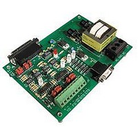
The AC8/AC8A/AC8B (Figure 6), is designed to operate inside an electrical enclosure. Mount the AC8 to a surface with screws
Inside Sales: (800) 321-OPTO • Product Support: (800) TEK-OPTO • (951) 695-3080 • Fax: (951) 695-3017 • Email: sales@opto22.com
© 2004 Opto 22. All rights reserved. All trademarks, trade names, logos, and service marks referenced herein belong to their respective companies.
Figure 6 - Dimensions and Layout of the AC8 Adapter Card
TRADITIONAL ADAPTER CARDS
INTERFACES
STAND-ALONE
page 8/11
Related parts for AC8
Image
Part Number
Description
Manufacturer
Datasheet
Request
R

Part Number:
Description:
Standard AC Input Module, 180 To 280 VAC Input Voltage Range, Voltage Input, 15 MA Output Current, 12 To 18 VDC Output Voltage, General
Manufacturer:
OPTO 22
Datasheet:

Part Number:
Description:
AC Output Module
Manufacturer:
OPTO 22
Datasheet:

Part Number:
Description:
SSR, PANEL MOUNT, 280VAC, 32VDC, 10A
Manufacturer:
OPTO 22
Datasheet:

Part Number:
Description:
SSR, PANEL MOUNT, 280VAC, 32VDC, 25A
Manufacturer:
OPTO 22
Datasheet:
Part Number:
Description:
SSR, PANEL MOUNT, 280VAC, 32VDC, 25A
Manufacturer:
OPTO 22
Datasheet:
Part Number:
Description:
SSR, PANEL MOUNT, 280VAC, 32VDC, 45A
Manufacturer:
OPTO 22
Datasheet:
Part Number:
Description:
SSR, PANEL MOUNT, 280VAC, 32VDC, 45A
Manufacturer:
OPTO 22
Datasheet:

Part Number:
Description:
Solid State Relays, Accessories
Manufacturer:
OPTO 22
Datasheet:
