CLM-ER11 FERROXCUBE, CLM-ER11 Datasheet - Page 2
CLM-ER11
Manufacturer Part Number
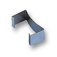
CLM-ER11
Description
CLAMP, ER11
Manufacturer
FERROXCUBE
Datasheet
1.ER11-3F3-S.pdf
(3 pages)
Specifications of CLM-ER11
Clip Style
Mounting Clamp
Length
11.5mm
Svhc
No SVHC (15-Dec-2010)
Termination Type
SMD
Lead Free Status / RoHS Status
Lead free / RoHS Compliant


Philips Components
Properties of core sets under power conditions
COIL FORMERS
General data
Winding data for ER11 coil former (SMD) with 10 solder pads
1997 Nov 21
handbook, full pagewidth
3F3
3F4
Coil former material
Pin material
Maximum operating temperature
Resistance to soldering heat
Solderability
GRADE
ER cores and accessories
Dimensions in mm.
NUMBER OF
SECTIONS
1
PARAMETER
H = 250 A/m;
10.6 max.
f = 25 kHz;
T = 100 C
B (mT) at
8.5
0.1
0.1
5.3
4.5
4
8
300
250
0.1
0.2
WINDING
AREA
(mm
2.8
CBW096
0.7
2
)
f = 100 kHz;
B ˆ
T = 100 C
= 100 mT;
Fig.2 ER11 coil former (SMD); 10-solder pads.
0.025
2.8
0.1
liquid crystal polymer (LCP), glass reinforced, flame retardant
in accordance with “UL 94V-0” ; UL file number E54705(M)
copper-tin alloy (CuSn), tin-lead alloy (SnPb) plated
155 C, “IEC 85” class F
“IEC 68-2-20” , Part 2, Test Tb, method 1B: 350 C, 3.5 s
“IEC 68-2-20” , Part 2, Test Ta, method 1: 235 C, 2 s
1.85
min.
MINIMUM
WINDING
WIDTH
(mm)
1.85
12.35 max.
f = 400 kHz;
B ˆ
T = 100 C
339
9.2
= 50 mT;
0.040
LENGTH OF
AVERAGE
CORE LOSS (W) at
TURN
(mm)
21.6
SPECIFICATION
max.
0.25
4.4
CPVS-ER11-1S-10P
B ˆ
T = 100 C
f = 1 MHz;
= 30 mT;
0.035
1.8
10
TYPE NUMBER
1.7
2
Product specification
B ˆ
T = 100 C
f = 3 MHz;
= 10 mT;
0.056
ER11
Related parts for CLM-ER11
Image
Part Number
Description
Manufacturer
Datasheet
Request
R

Part Number:
Description:
CLIP, CLM-E18/PLT18
Manufacturer:
FERROXCUBE
Datasheet:
Part Number:
Description:
CLIP, CLM-E22/PLT22
Manufacturer:
FERROXCUBE
Datasheet:

Part Number:
Description:
CLAMP, ER9.5
Manufacturer:
FERROXCUBE
Datasheet:
