FLUKE-1750 Fluke, FLUKE-1750 Datasheet - Page 8
FLUKE-1750
Manufacturer Part Number
FLUKE-1750
Description
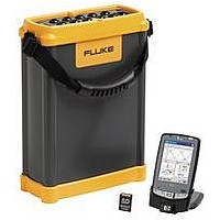
POWER RECORDER, 3 PHASE, 900V To 1100V
Manufacturer
Fluke
Datasheet
1.FLUKE-1750.pdf
(10 pages)
Specifications of FLUKE-1750
Analyzer Functions
Current, Power, Voltage
No. Of Channels
9
Voltage Range Rms
900V To 1100V
External Height
215mm
External Width
310mm
External Depth
35mm
Lead Free Status / RoHS Status
na


Voltage and current measurement accuracy
Transient voltage (impulse)
Dip (Sag) and Swell Measurements
Power Measurements
8 Fluke Corporation Fluke 1750 Three-Phase Power Recorder
RMS voltage
Measurement type
Measurement uncertainty
RMS current
Measurement type
Measurement uncertainty
Measurement type
Full scale
Sample resolution
Measurement uncertainty
Voltage swell (rms swell)
Measurement type
Displayed data
Measurement uncertainty
Voltage dip (rms sag)
Measurement type
Displayed data
Measurement uncertainty
Voltage dropout (interruption)
Measurement type
Calculated per IEEE1459 for best performance when distortions exist
Measurement type
Measurement accuracy
Frequency
Measurement range
Measurement source
Measurement accuracy
Power factor
Measurement range
Measurement accuracy
Displacement power factor
Measurement method
Measurement range
Measurement accuracy
Voltage unbalance and phase sequence
Measurement method
Harmonic voltage and current
Analysis window
True rms calculated continuously: every cycle, every 1/ cycle, and
every 10 or 1 cycles at 50 or 60 Hz respectively, as required by IEC 61000-4-30.
AC: ± 0. % reading ± 0.1 % full scale, above 50 V rms
DC: ± 0.5 % reading ± 0. % full scale, above 50 V dc
True rms calculated continuously: every cycle, every 1/ cycle, and
every 10 or 1 cycles at 50 or 60 Hz respectively, as required by standards
Ferromagnetic Clamps: ± (0.1 % full scale + 0. % reading + current sensor accuracy),
valid for 5 % to 100 % of current sensor range
Flexible Current Probes: ± (0.1 % full scale + 0.5 % reading + current sensor accuracy),
valid for 5 % to 100 % of current sensor range
Waveshape sampling
8000 V pk
00 nS
± 5 % reading ± 0 V (test parameters: 1000 V dc, 1000 V rms, 100 kHz)
True rms (one cycle calculation by overlapping each half cycle - voltage between lines is measured
for 3P3W lines and phase voltage is measured for 3P4W lines)
Amplitude and duration of swell
Same as rms voltage
True rms (one cycle calculation by overlapping each half cycle - voltage between lines is measured
for 3P3W lines and phase voltage is measured for 3P4W lines)
Amplitude and duration of dip or interruption
Same as rms voltage
Same as voltage dip
True rms calculated continuously: every cycle, and every 10 or 1 cycles at 50 or 60 Hz respectively,
as required by standards
+/- (voltage uncertainty + current uncertainty + current probe uncertainty)
4.5 to 69 Hz
Same as PLL synchronization source
± 10 mHz (10 to 110 % of range, with sine wave)
0.000 to 1.000
± 1 digit from the calculation of each measured value (±3 digits for total)
Calculated from the phase difference between voltage fundamental and current fundamental
- 1.000 (leading) to + 1.000 (lagging)
± 0.5 % reading ± % full scale ± 1 digit
Positive sequence voltage divided by negative sequence voltage, per IEC 61000-4-30
rectangular