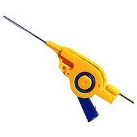
10467-68701 AGILENT TECHNOLOGIES, 10467-68701 Datasheet - Page 21

10467-68701
Manufacturer Part Number
10467-68701
Description
Test Lead Clip
Manufacturer
AGILENT TECHNOLOGIES
Datasheet
1.E2609B.pdf
(45 pages)
Specifications of 10467-68701
Lead Length
31.75mm
Voltage Rating
40V
For Use With
Infiniium Series Oscilliscopes
Lead Free Status / RoHS Status
na
High-Frequency Active Single-Ended Voltage Probes
Agilent 1156A/57A/58A High-Bandwidth, Active Single-Ended Voltage
Specifications
Operating Characteristics
Bandwidth (–3 dB)
System bandwidth (–3 dB)
Rise and fall time (10% to 90%)
calculated from t
Input capacitance
Input resistance [1]
Flatness, swept response
Flatness, step response
Dynamic range [2]
dc attenuation [1]
Zero offset error
referred to input [1]
Offset range [1]
Offset accuracy [1]
Noise referred to input
Propagation delay
Maximum input voltage
ESD tolerance
Temperature drift
[1] Denotes warranted specifications, all others are typical.
[2] For waveforms with edges > 3 ns, the dynamic range is > 12.0 V peak-to-peak.
[3] Installation category (over voltage category) I: Signal level, special equipment, or parts of equipment, telecommuni-
[4] Probe calibrated to scope channel (under Probes Setup menu).
Environmental Characteristics
Temperature
Humidity
cation, electronic, etc., with smaller transient overvoltage than installation category (overvoltage category) II.
r
= 0.35/bandwidth
1156A: > 1.5 GHz; 1157A: > 2.5 GHz; 1158A: > 4 GHz
1156A with MSO/DSO8104A, 54832B/D, 54833A/D
scope: 1 GHz;
1157A with 54852A scope: 2 GHz;
1157A with 54853A scope: 2.5 GHz;
1158A with 54854A scope: 4 GHz
1156A: < 233 ps; 1157A: < 140 ps; 1158A: < 88 ps
0.8 pF
100 kΩ 1%
0.2 dB: 100 kHz to 100 MHz;
0.4 dB: 100 MHz to 2.5 GHz;
2.0 dB: 2.5 GHz to 4.0 GHz
15% overshoot: 35 ps input edge;
10% overshoot: 75 ps input edge; 2%: 1 ns after edge
> 5.0 V peak-to-peak
10:1 ± 3% before calibration [4];
10:1 ± 1% after calibration [4]
< 30 mV before calibration [4];
< 5 mV after calibration [4]
±15.0 V
< 3% of setting before calibration [4];
1% of setting after calibration [4]
3.0 mVrms
5.5 ns
40 V peak, CAT I [3]
> 5 kV from 100 pF, 300 Ω HBM
Offset: < 1.0 mV/°C; Attenuation (Gain): 0.1 %/°C
Operating: 0° C to +55° C;
Non-operating: –40° C to +70° C
Operating: Up to 95% relative humidity
(non-condensing) at +40° C;
Non-operating: Up to 90% relative humidity at +65° C
Figure 3.11. Notice how closely output
matches input. Graph shows V
when driven from a 25 Ω source.
Figure 3.12. The flat response means the
waveform on the scope screen will match
the waveform at the probe tip—across
an entire 4 GHz bandwidth. Graph shows
response (V
out
/V
in
).
in
and V
out
21


