BS170G ON Semiconductor, BS170G Datasheet

MOSFET N-CH 60V 500MA TO-92

BS170G

Manufacturer Part Number
BS170G
Description
MOSFET N-CH 60V 500MA TO-92
Manufacturer
ON Semiconductor
Type
Small Signalr
Datasheets

Specifications of BS170G

Fet Type
MOSFET N-Channel, Metal Oxide
Fet Feature
Standard
Rds On (max) @ Id, Vgs
5 Ohm @ 200mA, 10V
Drain To Source Voltage (vdss)
60V
Current - Continuous Drain (id) @ 25° C
500mA
Vgs(th) (max) @ Id
3V @ 1mA
Input Capacitance (ciss) @ Vds
60pF @ 10V
Power - Max
350mW
Mounting Type
Through Hole
Package / Case
TO-92-3 (Standard Body), TO-226
Configuration
Single
Transistor Polarity
N-Channel
Resistance Drain-source Rds (on)
5 Ohm @ 10 V
Forward Transconductance Gfs (max / Min)
0.2 S
Drain-source Breakdown Voltage
60 V
Gate-source Breakdown Voltage
+/- 20 V
Continuous Drain Current
0.5 A
Power Dissipation
350 mW
Maximum Operating Temperature
+ 150 C
Mounting Style
Through Hole
Minimum Operating Temperature
- 55 C
Current, Drain
0.5 A
Package Type
TO-92 (TO-226)
Polarization
N-Channel
Resistance, Drain To Source On
1.8 Ohms
Temperature, Operating, Maximum
+150 °C
Temperature, Operating, Minimum
-55 °C
Transconductance, Forward
200 Millimhos
Voltage, Breakdown, Drain To Source
90 V
Voltage, Gate To Source
±20 VDC
Number Of Elements
1
Polarity
N
Channel Mode
Enhancement
Drain-source On-res
5Ohm
Drain-source On-volt
60V
Gate-source Voltage (max)
±20V
Operating Temp Range
-55C to 150C
Operating Temperature Classification
Military
Mounting
Through Hole
Pin Count
3
Lead Free Status / RoHS Status
Lead free / RoHS Compliant
Gate Charge (qg) @ Vgs
-
Lead Free Status / Rohs Status
Lead free / RoHS Compliant
Other names
BS170G
BS170GOS

Available stocks

Company
Part Number
Manufacturer
Quantity
Price
Part Number:
BS170G
Manufacturer:
ON Semiconductor
Quantity:
4 450
Part Number:
BS170G
Manufacturer:
ON/安森美
Quantity:
20 000
Part Number:
BS170G.
Manufacturer:
ON/安森美
Quantity:
20 000
BS170G
Small Signal MOSFET
500 mA, 60 Volts
N−Channel TO−92 (TO−226)
Features
Stresses exceeding Maximum Ratings may damage the device. Maximum
Ratings are stress ratings only. Functional operation above the Recommended
Operating Conditions is not implied. Extended exposure to stresses above the
Recommended Operating Conditions may affect device reliability.
NOTE: The Power Dissipation of the package may result in a lower continuous
*For additional information on our Pb−Free strategy and soldering details, please
© Semiconductor Components Industries, LLC, 2011
April, 2011 − Rev. 6
MAXIMUM RATINGS
download the ON Semiconductor Soldering and Mounting Techniques
Reference Manual, SOLDERRM/D.
Drain −Source Voltage
Gate−Source Voltage
Drain Current (Note)
Total Device Dissipation @ T
Operating and Storage Junction
This is a Pb−Free Device*
− Continuous
− Non−repetitive (t
Temperature Range
drain current.
Rating
p
≤ 50 ms)
A
= 25°C
Symbol
T
V
J
V
V
GSM
P
, T
I
DS
GS
D
D
stg
−55 to
Value
+150
± 20
± 40
350
0.5
60
1
Unit
Vdc
Vdc
Vpk
Adc
mW
°C
See detailed ordering and shipping information in the package
dimensions section on page 2 of this data sheet.
1 2
(Note: Microdot may be in either location)
3
ORDERING INFORMATION
A
Y
WW
G
500 mA, 60 Volts
MARKING DIAGRAM
& PIN ASSIGNMENT
R
G
http://onsemi.com
Drain
DS(on)
1
= Assembly Location
= Year
= Work Week
= Pb−Free Package
AYWWG
N−Channel
BS170
Gate
TO−92 (TO−226)
G
Publication Order Number:
D
2
= 5.0 W
STYLE 30
CASE 29
S
3
Source
BS170/D

Related parts for BS170G

BS170G Summary of contents

Page 1

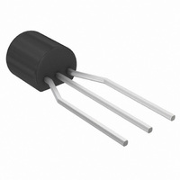
... BS170G Small Signal MOSFET 500 mA, 60 Volts N−Channel TO−92 (TO−226) Features • This is a Pb−Free Device* MAXIMUM RATINGS Rating Drain −Source Voltage Gate−Source Voltage − Continuous − Non−repetitive (t ≤ 50 ms) p Drain Current (Note) Total Device Dissipation @ T = 25°C A Operating and Storage Junction Temperature Range Stresses exceeding Maximum Ratings may damage the device ...

Page 2

... Adc) See Figure Pulse Test: Pulse Width v 300 ms, Duty Cycle v 2.0%. ORDERING INFORMATION Device BS170G BS170RLRAG †For information on tape and reel specifications, including part orientation and tape sizes, please refer to our Tape and Reel Packaging Specifications Brochure, BRD8011/ 25°C unless otherwise noted) ...

Page 3

V in PULSE GENERATOR 1.0 MW Figure 1. Switching Test Circuit 2.0 1.6 1.2 0.8 0 JUNCTION TEMPERATURE (°C) J Figure 3. V Normalized versus Temperature GS(th) 2.0 ...

Page 4

... Opportunity/Affirmative Action Employer. This literature is subject to all applicable copyright laws and is not for resale in any manner. PUBLICATION ORDERING INFORMATION LITERATURE FULFILLMENT: Literature Distribution Center for ON Semiconductor P.O. Box 5163, Denver, Colorado 80217 USA Phone: 303−675−2175 or 800−344−3860 Toll Free USA/Canada Fax: 303− ...

Related keywords