XS5C-D4S2 Omron, XS5C-D4S2 Datasheet - Page 15
XS5C-D4S2
Manufacturer Part Number
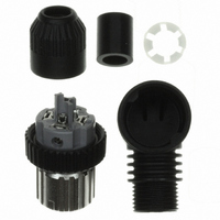
XS5C-D4S2
Description
Sensor I/O Connector
Manufacturer
Omron
Series
XS5r
Datasheet
1.XS5F-D421-D80-A.pdf
(18 pages)
Specifications of XS5C-D4S2
Connector Type
Receptacle, Female Sockets
Number Of Positions
4
Mounting Type
Free Hanging (In-Line), Right Angle
Termination
Screw
Fastening Type
Bayonet Lock
Orientation
Keyed
Ingress Protection
IP67 - Dust Tight, Waterproof
Shell Material, Finish
Brass, Nickel Plated
Product Type
Connectors
Contact Style
Socket (Female)
Shell Style
Receptacle
Number Of Positions / Contacts
4
Mounting Style
Free Hanging
Termination Style
Screw
Leaded Process Compatible
Yes
Contact Material
Brass
Connector Mounting
Free Hanging
No. Of Contacts
4
Contact Termination
Screw
Gender
Receptacle
Contact Gender
Socket (Female)
Contact Plating
Gold
Rohs Compliant
Yes
Lead Free Status / RoHS Status
Lead free / RoHS Compliant
Features
-
Shell Size - Insert
-
Shell Size, Military
-
Lead Free Status / Rohs Status
Lead free / RoHS Compliant
Other names
OR795
XS5CD4S2
XS5CD4S2


Insertion
• Five-pole Connectors
Cable End Processing
• Four-pole Connectors
• Tentatively insert the pins to the pin block holes so that the key on
Screw-on Connectors
• Loosen the screws on pins 1 to 4 and insert the cores according to
• Use the dedicated Screwdriver (XW4Z-00B)* and tighten the
• Strip the cable sheath for a total of 15 mm and strip the core
• Connect the core to pin 5 (in the center) first.
• Insert the core from the side of the hold with the tab and tighten the
the pin block will coincide with the key groove on the pin clamp.
Then insert the cable along with the pin clamp.
the pin numbers.
screws securely so that the cores do not pull out (tightening torque:
0.15 to 0.2 N·m).
covering for 8 mm for the core to connect to pin 5.
screw securely (tightening torque: 0.15 to 0.2 N·m), and then cut
off the excess wire with wire cutters.
Pin Block
Screw
Key
8
screwdriver
Dedicated
7
8
12
±0.5
12
XS5C use XS5G use
Pin Clamp
Conductors for
pins 1 to 4
Conductors for
pin 5
6
±0.5
Tab
Key groove Key groove
Screw
screwdriver
Dedicated
Connecting Shielded Cables to Five-pole Connectors
* When tightening the screws, use the dedicated XW4Z-00B
(4) Inserting Pin Block
• Bend the cable as shown below, attached the enclosed insulation
• Connect the cores to pins 1 to 4.
• Place the insulation tub on the drain line of the shield and connect
• Tighten the screw and then check visually to see if there is
• Connect the cores to pins 1 to 4.
• Mount the cover to the pin block so that the triangle mark on the pin
• If the cover is used for an Angled model, the relationship between
• Fully insert the positioning key until the positioning key is hidden by
Screwdriver that matches with the screw-slot dimensions.
cap, and then strip the other cores.
it to the terminal.
insulation between the cores.
block will coincide with the triangle mark on the cover.
the position of the polarity key on the engaged side and cable
connection direction will be determined by the direction in which
the positioning key is inserted into the cover, which can be rotated
by 90°.
the casing.
Pin Block
(Soldering Model)
(Crimping Model)
Polarity key
Lock spring
Positioning key
(triangle mark)
XW4Z-00B
Screwdriver
Drain line
O-ring
Insulation tube
Insulation cap
(Angled Model)
Cover
(Straight Model)
Triangle mark
XS5
15
Related parts for XS5C-D4S2
Image
Part Number
Description
Manufacturer
Datasheet
Request
R

Part Number:
Description:
Waterproof Sensor Connector
Manufacturer:
Omron
Datasheet:
Part Number:
Description:
Sensor I/O Connector
Manufacturer:
Omron
Datasheet:

Part Number:
Description:
Sensor I/O Connector
Manufacturer:
Omron
Datasheet:
Part Number:
Description:
Sensor I/O Connector
Manufacturer:
Omron
Datasheet:

Part Number:
Description:
G6S-2GLow Signal Relay
Manufacturer:
Omron Corporation
Datasheet:
Part Number:
Description:
Compact, Low-cost, SSR Switching 5 to 20 A
Manufacturer:
Omron Corporation
Datasheet:
Part Number:
Description:
Manufacturer:
Omron Corporation
Datasheet:
Part Number:
Description:
Manufacturer:
Omron Corporation
Datasheet:
Part Number:
Description:
Manufacturer:
Omron Corporation
Datasheet:
Part Number:
Description:
Manufacturer:
Omron Corporation
Datasheet: