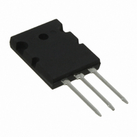
IXKK85N60C IXYS, IXKK85N60C Datasheet - Page 2

IXKK85N60C
Manufacturer Part Number
IXKK85N60C
Description
MOSFET N-CH 600V 85A TO-264
Manufacturer
IXYS
Series
CoolMOS™r
Datasheet
1.IXKK85N60C.pdf
(4 pages)
Specifications of IXKK85N60C
Fet Type
MOSFET N-Channel, Metal Oxide
Fet Feature
Standard
Rds On (max) @ Id, Vgs
36 mOhm @ 55A, 10V
Drain To Source Voltage (vdss)
600V
Current - Continuous Drain (id) @ 25° C
85A
Vgs(th) (max) @ Id
4V @ 4mA
Gate Charge (qg) @ Vgs
650nC @ 10V
Mounting Type
Through Hole
Package / Case
TO-264
Configuration
Single
Transistor Polarity
N-Channel
Resistance Drain-source Rds (on)
0.036 Ohms
Drain-source Breakdown Voltage
600 V
Gate-source Breakdown Voltage
+/- 20 V
Continuous Drain Current
85 A
Power Dissipation
700 W
Maximum Operating Temperature
+ 150 C
Mounting Style
Through Hole
Minimum Operating Temperature
- 55 C
Vdss, Max, (v)
600
Id(cont), Tc=25°c, (a)
85
Rds(on), Max, Tj=25°c, (?)
0.036
Ciss, Typ, (pf)
13600
Qg, Typ, (nc)
500
Trr, Max, (ns)
-
Trr, Typ, (ns)
580
Pd, (w)
700
Rthjc, Max, (k/w)
0.18
Visol, Rms, (v)
-
Package Style
TO-264
Lead Free Status / RoHS Status
Lead free / RoHS Compliant
Power - Max
-
Lead Free Status / Rohs Status
Details
Available stocks
Company
Part Number
Manufacturer
Quantity
Price
Company:
Part Number:
IXKK85N60C
Manufacturer:
NXP
Quantity:
5 000
Part Number:
IXKK85N60C
Manufacturer:
IXYS/艾赛斯
Quantity:
20 000
TO-264 Outline
IXYS reserves the right to change limits, test conditions and dimensions.
© 2010 IXYS All rights reserved
Source-Drain Diode
Symbol
I
I
V
t
Q
I
Component
Symbol
T
T
M
Symbol
R
Weight
S
SM
RM
rr
SD
VJ
stg
thCH
RM
d
Conditions
V
I
I
Conditions
operating
mounting torque
Conditions
with heatsink compound
F
F
GS
= 85 A; V
= 85 A; -di
= 0 V
GS
F
/dt = 200 A/µs; V
= 0 V
R
(T
= 350 V
VJ
= 25°C, unless otherwise specified)
min.
min.
Characteristic Values
Characteristic Values
Maximum Ratings
0.15
typ.
typ.
580
140
46
10
-55...+150
-55...+150
0.8 ... 1.2
NOTE : 1. This drawing meets all dimension s
max.
max.
250
1.2
85
SYM
b1
b2
C
D
e
P
Q
Q1
R
R1
S
b
E
L
L1
L2
L3
A
A1
2. All metal su rface are solder pl ated
K/W
Nm
µC
°C
°C
ns
A
A
V
A
g
TO-264AAexcept L, L1, L2, L3.
except trimmed a rea.
requirement of JEDEC outline s
1.007
MIN
.110
.185
.102
.037
.087
.017
.760
.193
.075
.000
.122
.240
.330
.155
.085
.243
INCHES
.215
BSC
1.047
.209
.118
.055
.102
.126
.029
.799
.096
.083
.004
.138
.256
.346
.187
.093
.253
.201
MAX
IXKK 85N60C
25.58
19.30
4.70
2.59
2.79
MIN
2.21
4.90
2.24
0.00
3.10
6.10
8.38
3.94
2.16
6.17
MILLIMETERS
0.43
0.94
1.90
5.46
BSC
26.59
20.29
MAX
6.50
8.79
2.36
5.31
3.00
2.59
3.20
2.10
0.10
3.51
4.75
6.43
0.74
5.10
2.44
20100315c
1.40
2 - 4


