IRLMS2002 International Rectifier, IRLMS2002 Datasheet
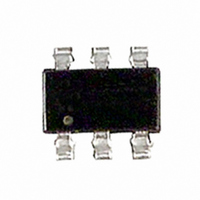
MOSFET N-CH 20V 6.5A TSOP-6

IRLMS2002

Manufacturer Part Number
IRLMS2002
Description
MOSFET N-CH 20V 6.5A TSOP-6
Manufacturer
International Rectifier
Series
HEXFET®r
Datasheet

Specifications of IRLMS2002

Fet Type
MOSFET N-Channel, Metal Oxide
Fet Feature
Logic Level Gate
Rds On (max) @ Id, Vgs
30 mOhm @ 6.5A, 4.5V
Drain To Source Voltage (vdss)
20V
Current - Continuous Drain (id) @ 25° C
6.5A
Vgs(th) (max) @ Id
1.2V @ 250µA
Gate Charge (qg) @ Vgs
22nC @ 5V
Input Capacitance (ciss) @ Vds
1310pF @ 15V
Power - Max
2W
Mounting Type
Surface Mount
Package / Case
Micro6™(TSOP-6)
Lead Free Status / RoHS Status
Contains lead / RoHS non-compliant

Available stocks

Company
Part Number
Manufacturer
Quantity
Price
Part Number:
IRLMS2002
Manufacturer:
IR
Quantity:
20 000
Part Number:
IRLMS2002(2G1P)
Manufacturer:
Fairchild
Quantity:
750
Part Number:
IRLMS2002TR
Manufacturer:
IR
Quantity:
9 000
Part Number:
IRLMS2002TR
Manufacturer:
IR
Quantity:
20 000
Part Number:
IRLMS2002TRPBF
Manufacturer:
IR
Quantity:
21 600
Part Number:
IRLMS2002TRPBF
Manufacturer:
IR
Quantity:
9 000
Part Number:
IRLMS2002TRPBF
Manufacturer:
IR
Quantity:
20 000
l
l
l
l
l
Thermal Resistance
Description
These N-Channel MOSFETs from International Rectifier
utilize advanced processing techniques to achieve the
extremely low on-resistance per silicon area. This benefit
provides the designer with an extremely efficient device for
use in battery and load management applications.
The
produces a HEXFET power MOSFET with R
less than a similar size SOT-23. This package is ideal for
applications where printed circuit board space is at a
premium. It's unique thermal design and R
enables a current-handling increase of nearly 300%
compared to the SOT-23.
www.irf.com
V
I
I
I
P
P
V
T
R
D
D
DM
J,
DS
D
D
GS
@ T
@ T
JA
Ultra Low On-Resistance
N-Channel MOSFET
Surface Mount
Available in Tape & Reel
2.5V Rated
@T
@T
T
STG
Micro6
A
A
A
A
= 70°C
= 25°C
= 25°C
= 70°C
package with its customized leadframe
Drain- Source Voltage
Continuous Drain Current, V
Pulsed Drain Current 
Power Dissipation
Power Dissipation
Linear Derating Factor
Gate-to-Source Voltage
Junction and Storage Temperature Range
Maximum Junction-to-Ambient
Parameter
Parameter
DS(on)
GS
GS
ƒ
DS(on)
@ 4.5V
@ 4.5V
reduction
60%
G
D
D
1
2
3
Top View
HEXFET Power MOSFET
6
5
4
-55 to + 150
IRLMS2002
Max.
Max.
0.016
62.5
± 12
6.5
5.2
2.0
1.3
D
S
20
20
D
Micro6
A
R
DS(on)
V
DSS
= 0.030
= 20V
Units
Units
W/°C
°C/W
°C
V
A
V
1
01/13/03

Related parts for IRLMS2002

IRLMS2002 Summary of contents

Page 1

... Junction and Storage Temperature Range J, STG Thermal Resistance Parameter R Maximum Junction-to-Ambient JA www.irf.com HEXFET Power MOSFET Top View 60% DS(on) reduction DS(on 4. 150 ƒ IRLMS2002 20V DSS 0.030 S DS(on) Micro6 Max. Units 20 V 6.5 5 2.0 1.3 0.016 W/°C ± °C Max. Units 62.5 ° ...

Page 2

Electrical Characteristics @ T Parameter V Drain-to-Source Breakdown Voltage (BR)DSS Breakdown Voltage Temp. Coefficient (BR)DSS J R Static Drain-to-Source On-Resistance DS(on) V Gate Threshold Voltage GS(th) g Forward Transconductance fs I Drain-to-Source Leakage Current DSS Gate-to-Source Forward ...

Page 3

VGS TOP 7.50V 5.00V 4.00V 3.50V 3.00V 2.50V 2.00V BOTTOM 1.50V 10 1.50V 20µs PULSE WIDTH 0 Drain-to-Source Voltage (V) DS Fig 1. Typical Output Characteristics 100 ° ...

Page 4

1MHz iss rss 1600 oss iss 1200 800 400 C oss C rss ...

Page 5

T , Case Temperature ( C) C Fig 9. Maximum Drain Current Vs. Case Temperature 100 D = 0.50 0.20 10 0.10 0.05 0.02 1 0.01 SINGLE PULSE (THERMAL ...

Page 6

Id = 5.3A 0.020 2.0 3.0 4.0 5.0 V GS, Gate -to -Source Voltage ( V ) Fig 12. Typical On-Resistance Vs. Gate Voltage 6 0.10 0.08 0.06 0.04 0.02 0 6.0 7.0 8.0 Fig 13. ...

Page 7

3.00 (.118 ) -B- 2.80 (.111 ) 1.75 (.068 ) 3.00 (.118 ) 1.50 (.060 ) 2.60 (.103 ) - 0.95 ( .0375 ) 0.50 (.019 ) 6X 2X 0.35 (.014 ) 0.15 (.006 ...

Page 8

Notes: This part marking information applies to devices produced before 02/26/2001 EXAMPLE: THIS IS AN IRLMS6702 PART NUMBER WAFER LOT NUMBER CODE PART NUMBER CODE REFERENCE IRLMS 1902 2B = IRLMS 1503 2C = IRLMS 6702 2D = ...

Related keywords