NTD4858N-1G ON Semiconductor, NTD4858N-1G Datasheet - Page 7
NTD4858N-1G
Manufacturer Part Number
NTD4858N-1G
Description
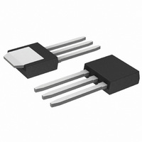
MOSFET N-CH 25V 11.2A IPAK
Manufacturer
ON Semiconductor
Datasheet
1.NTD4858NT4G.pdf
(8 pages)
Specifications of NTD4858N-1G
Fet Type
MOSFET N-Channel, Metal Oxide
Fet Feature
Logic Level Gate
Rds On (max) @ Id, Vgs
6.2 mOhm @ 30A, 10V
Drain To Source Voltage (vdss)
25V
Current - Continuous Drain (id) @ 25° C
11.2A
Vgs(th) (max) @ Id
2.5V @ 250µA
Gate Charge (qg) @ Vgs
19.2nC @ 4.5V
Input Capacitance (ciss) @ Vds
1563pF @ 12V
Power - Max
1.3W
Mounting Type
Through Hole
Package / Case
IPak, TO-251, DPak, VPak (3 straight leads + tab)
Configuration
Single
Transistor Polarity
N-Channel
Resistance Drain-source Rds (on)
7.3 mOhms
Forward Transconductance Gfs (max / Min)
55 S
Drain-source Breakdown Voltage
25 V
Gate-source Breakdown Voltage
+/- 20 V
Continuous Drain Current
11.2 A
Power Dissipation
2 W
Maximum Operating Temperature
+ 175 C
Mounting Style
Through Hole
Minimum Operating Temperature
- 55 C
Lead Free Status / RoHS Status
Lead free / RoHS Compliant
Available stocks
Company
Part Number
Manufacturer
Quantity
Price
Company:

Part Number:
NTD4858N-1G
Manufacturer:
ON Semiconductor
Quantity:
135


L3
L4
b2
e
1
b3
4
2
E
3
b
A
D
0.005 (0.13)
B
*For additional information on our Pb--Free strategy and soldering
M
DETAIL A
details, please download the ON Semiconductor Soldering and
Mounting Techniques Reference Manual, SOLDERRM/D.
C
c
0.228
5.80
L2
A
GAUGE
PLANE
PACKAGE DIMENSIONS
DPAK (SINGLE GUAGE)
ROTATED 90 CW
SOLDERING FOOTPRINT*
c2
DETAIL A
H
C
http://onsemi.com
0.244
L
6.20
CASE 369AA--01
L1
ISSUE B
°
7
0.102
2.58
A1
H
0.118
3.00
0.063
1.60
C
SCALE 3:1
Z
SEATING
PLANE
0.243
6.17
NOTES:
1. DIMENSIONING AND TOLERANCING PER ASME
2. CONTROLLING DIMENSION: INCHES.
3. THERMAL PAD CONTOUR OPTIONAL WITHIN
4. DIMENSIONS D AND E DO NOT INCLUDE MOLD
5. DIMENSIONS D AND E ARE DETERMINED AT THE
6. DATUMS A AND B ARE DETERMINED AT DATUM
inches
mm
Y14.5M, 1994.
DIMENSIONS b3, L3 and Z.
FLASH, PROTRUSIONS, OR BURRS. MOLD
FLASH, PROTRUSIONS, OR GATE BURRS SHALL
NOT EXCEED 0.006 INCHES PER SIDE.
OUTERMOST EXTREMES OF THE PLASTIC BODY.
PLANE H.
STYLE 2:
DIM
A1
b2
b3
c2
L1
L2
L3
L4
PIN 1. GATE
A
b
D
E
H
L
Z
c
e
2. DRAIN
3. SOURCE
4. DRAIN
0.086
0.000
0.025
0.030
0.180
0.018
0.018
0.235
0.250
0.370
0.055
0.035
0.155
MIN
------
0.090 BSC
0.108 REF
0.020 BSC
INCHES
0.094
0.005
0.035
0.045
0.215
0.024
0.024
0.245
0.265
0.410
0.070
0.050
0.040
MAX
------
MILLIMETERS
2.18
0.00
0.63
0.76
4.57
0.46
0.46
5.97
6.35
9.40
1.40
0.89
3.93
MIN
------
2.29 BSC
0.51 BSC
2.74 REF
10.41
MAX
2.38
0.13
0.89
1.14
5.46
0.61
0.61
6.22
6.73
1.78
1.27
1.01
------
Related parts for NTD4858N-1G
Image
Part Number
Description
Manufacturer
Datasheet
Request
R

Part Number:
Description:
ON Semiconductor [VOLTAGE REGULATOR]
Manufacturer:
ON Semiconductor
Datasheet:
Part Number:
Description:
357-036-542-201 CARDEDGE 36POS DL .156 BLK LOPRO
Manufacturer:
ON Semiconductor
Datasheet:
Part Number:
Description:
357-036-542-201 CARDEDGE 36POS DL .156 BLK LOPRO
Manufacturer:
ON Semiconductor
Datasheet:
Part Number:
Description:
357-036-542-201 CARDEDGE 36POS DL .156 BLK LOPRO
Manufacturer:
ON Semiconductor
Datasheet:
Part Number:
Description:
357-036-542-201 CARDEDGE 36POS DL .156 BLK LOPRO
Manufacturer:
ON Semiconductor
Datasheet:
Part Number:
Description:
357-036-542-201 CARDEDGE 36POS DL .156 BLK LOPRO
Manufacturer:
ON Semiconductor
Datasheet:
Part Number:
Description:
357-036-542-201 CARDEDGE 36POS DL .156 BLK LOPRO
Manufacturer:
ON Semiconductor
Datasheet:
Part Number:
Description:
357-036-542-201 CARDEDGE 36POS DL .156 BLK LOPRO
Manufacturer:
ON Semiconductor
Datasheet:
Part Number:
Description:
357-036-542-201 CARDEDGE 36POS DL .156 BLK LOPRO
Manufacturer:
ON Semiconductor
Datasheet:
Part Number:
Description:
357-036-542-201 CARDEDGE 36POS DL .156 BLK LOPRO
Manufacturer:
ON Semiconductor
Datasheet:
Part Number:
Description:
357-036-542-201 CARDEDGE 36POS DL .156 BLK LOPRO
Manufacturer:
ON Semiconductor
Datasheet:
Part Number:
Description:
Manufacturer:
ON Semiconductor
Datasheet:
Part Number:
Description:
Manufacturer:
ON Semiconductor
Datasheet:
Part Number:
Description:
Manufacturer:
ON Semiconductor
Datasheet: