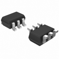
HSMS-282R-TR1G Avago Technologies US Inc., HSMS-282R-TR1G Datasheet - Page 7

HSMS-282R-TR1G
Manufacturer Part Number
HSMS-282R-TR1G
Description
DIODE SCHOTTKY RF 15V SOT-363
Manufacturer
Avago Technologies US Inc.
Datasheet
1.HSMS-2823-BLKG.pdf
(15 pages)
Specifications of HSMS-282R-TR1G
Diode Type
Schottky - 2 Pair Series Connection
Voltage - Peak Reverse (max)
15V
Current - Max
1A
Capacitance @ Vr, F
1pF @ 0V, 1MHz
Resistance @ If, F
12 Ohm @ 5mA, 1MHz
Package / Case
SC-70-6, SC-88, SOT-363
Capacitance Ct
1pF
Diode Case Style
SOT-363
No. Of Pins
6
Series Resistance @ If
6ohm
Peak Reflow Compatible (260 C)
Yes
Reel Quantity
3000
Termination Type
SMD
Forward Voltage
340mV
Breakdown Voltage
15V
Rohs Compliant
Yes
Filter Terminals
SMD
Leaded Process Compatible
Yes
Lead Free Status / RoHS Status
Lead free / RoHS Compliant
Power Dissipation (max)
-
Lead Free Status / RoHS Status
Lead free / RoHS Compliant, Lead free / RoHS Compliant
Available stocks
Company
Part Number
Manufacturer
Quantity
Price
Company:
Part Number:
HSMS-282R-TR1G
Manufacturer:
AVAGO
Quantity:
2 500
Part Number:
HSMS-282R-TR1G
Manufacturer:
AVAGO/安华高
Quantity:
20 000
7
Figure 14. Fabrication of Avago Diode Pairs.
In high power applications, coupling of RF energy from
the detector diode to the reference diode can introduce
error in the differential detector. The HSMS‑282K diode
pair, in the six lead SOT‑363 package, has a copper bar
between the diodes that adds 10 dB of additional isola‑
tion between them. As this part is manufactured in the
SOT‑363 package it also provides the benefit of being
40% smaller than larger SOT‑143 devices. The HSMS‑282K
is illustrated in Figure 15 — note that the ground connec‑
tions must be made as close to the package as possible to
minimize stray inductance to ground.
Figure 15. High Power Differential Detector.
The concept of the voltage doubler can be applied to the
differential detector, permitting twice the output voltage
for a given input power (as well as improving input im‑
pedance and suppressing second harmonics).
Figure 16. Voltage Doubler Differential Detector.
PA
matching
network
bias
detector diode
reference diode
to differential amplifier
HSMS-282K
HSMS-2825
HSMS-2825
differential
amplifier
V
bias
Figure 17. Voltage Doubler Differential Detector.
However, care must be taken to assure that the two refer‑
ence diodes closely match the two detector diodes. One
possible configuration is given in Figure 16, using two
HSMS‑2825. Board space can be saved through the use of
the HSMS‑282P open bridge quad, as shown in Figure 17.
While the differential detector works well over tempera‑
ture, another design approach
detectors. See Figure 18 for the schematic and a physical
layout of the circuit. In this design, the two 4.7 KΩ resis‑
tors and diode D2 act as a variable power divider, assuring
constant output voltage over temperature and improving
output linearity.
68 Ω
Figure 18. Temperature Compensated Detector.
In certain applications, such as a dual‑band cellphone
handset operating at both 900 and 1800 MHz, the second
harmonics generated in the power control output detec‑
tor when the handset is working at 900 MHz can cause
problems. A filter at the output can reduce unwanted
emissions at 1800 MHz in this case, but a lower cost so‑
lution is available
19, this circuit uses diode D2 and its associated passive
components to cancel all even order harmonics at the
detector’s RF input. Diodes D3 and D4 provide tempera‑
ture compensation as described above. All four diodes are
contained in a single HSMS‑ 282R package, as illustrated
in the layout shown in Figure 20.
[3] Hans Eriksson and Raymond W. Waugh, “A Temperature Compensated
RF
HSMS-282K
HSMS-2825
in
matching
Linear Diode Detector, ” to be published.
network
or
D1
33 pF
HSMS-282K
4.7 KΩ
bias
[4]
RF
4.7 KΩ
D2
. Illustrated schematically in Figure
HSMS-282P
V
in
o
68 Ω
differential
amplifier
[3]
works well for large signal
4.7 KΩ
33 pF
V
o


