601966-6 Tyco Electronics, 601966-6 Datasheet - Page 14
601966-6
Manufacturer Part Number
601966-6
Description
Connector Accessories Loose Piece Tool Positioner
Manufacturer
Tyco Electronics
Type
Positionerr
Specifications of 601966-6
Accessory Type
Positioner
Product
Crimping, Stripping & Cutting Tools & Drills
Description/function
Hand crimp tool assembly
Lead Free Status / RoHS Status
Not applicable / Not applicable
For Use With/related Products
A9977
For Use With
1-204370-3 - CONN D-SUB PIN 22-28AWG CRIMP AUA34528 - CONN PIN 22-28AWG CRIMP GOLDA34484 - CONN PIN 22-28AWG 50 GOLD
Lead Free Status / Rohs Status
Lead free / RoHS Compliant
Other names
A34490


3. TOOLING ASSEMBLY
3.1. Installing Positioner
Refer to Figure 4, and proceed as follows:
14 of 17
CAUTION
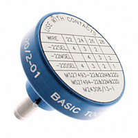
Data
Plate
Outer
Rim
1. Squeeze the tool handles together, then allow
the handles to FULLY open.
2. Insert the post of the positioner into the hole in
the back of the tool. Make sure that the bayonet
pin enters the slot in the retainer ring of the tool.
3. Firmly grip the outer rim of the positioner and
push until the spring inside the positioner is
depressed, then rotate the positioner clockwise
until it stops.
4. Insert the tool safety clip into the retainer ring to
lock the positioner in place.
5. Determine the selector setting according to the
contact size and wire size listed in Figure 3 (or
Back of Tool
!
Selector Knob
and Dial
Bayonet
Pin
The tool handles must be fully opened when
installing the positioner; otherwise, damage to
the tool will occur.
Installing Positioner
Figure 4
Safety
Clip
Tool Handles
Post
Retainer Ring
(Hidden)
Positioner
Installed
Ratchet
3.2. Installing Turret Head
Refer to Figure 5, and proceed as follows:
CAUTION
CAUTION
Turret in Locked
Position
Back of Tool
refer to the data plate on the positioner. Pull the
selector knob and turn to the proper setting.
1. Squeeze the tool handles together, then allow
the handles to FULLY open.
2. Depress the turret trigger to release the turret
from the index position (the turret should be
extended).
Turret
Extended
!
!
Selector Knob
and Dial
The tool handles must be fully opened when
changing the positioner selector setting;
otherwise, damage to the tool will occur.
The tool handles must be fully opened when
installing the positioner; otherwise, damage to
the tool will occur.
Retainer Ring
(Hidden)
Index
Mark
Installing Turret Head
Positioner
Figure 5
Tool Handles
Socket Head Cap
Screw (2 Places)
Data
Plate
Turret Trigger
Turret Head
Installed
Back of
Turret Head
408- 7516
Rev E
Related parts for 601966-6
Image
Part Number
Description
Manufacturer
Datasheet
Request
R

Part Number:
Description:
Connector Accessories Loose Piece Tool Positioner
Manufacturer:
Tyco Electronics
Datasheet:

Part Number:
Description:
CONN RECT FASTON 16-20 AWG .187
Manufacturer:
Tyco Electronics
Datasheet:

Part Number:
Description:
TERMINAL FEMALE DISCONNECT 0.187IN CRIMP
Manufacturer:
Tyco Electronics
Datasheet:

Part Number:
Description:
TERM RCPT FAST 20-16AWG .187
Manufacturer:
Tyco Electronics
Datasheet:
Part Number:
Description:
Battery Interconnection System for Portable Electronics; BU CONN FS6 8POS DIP TYPE ASSY ( AMP )
Manufacturer:
Tyco Electronics
Part Number:
Description:
Manufacturer:
Tyco Electronics
Datasheet:
Part Number:
Description:
Manufacturer:
Tyco Electronics
Datasheet: