ATF-541M4-TR1 Avago Technologies US Inc., ATF-541M4-TR1 Datasheet
ATF-541M4-TR1
Specifications of ATF-541M4-TR1
Available stocks


Related parts for ATF-541M4-TR1


ATF-541M4-TR1 Summary of contents
Page 1
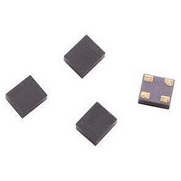
... Avago Technologies’ ATF‑541M4 is a high linearity, low noise, single supply E‑PHEMT housed in a miniature lead‑ less package. The ATF‑541M4’s small size and low profile makes it ideal for the design of hybrid module and other space‑con‑ straint devices. ...
Page 2
... ATF-541M4 Absolute Maximum Ratings [1] Symbol Parameter V Drain‑Source Voltage [ Gate‑Source Voltage [ Gate Drain Voltage [ Drain Current [ Gate Current [ Total Power Dissipation [3] diss P RF Input Power [5] in max. T Channel Temperature CH T Storage Temperature STG θ Thermal Resistance [4] jc 120 0.7V 100 0 ...
Page 3
... ATF-541M4 Electrical Specifications T = 25°C, RF parameters measured in a test circuit for a typical device A Symbol Parameter and Test Condition Vgs Operational Gate Voltage Vth Threshold Voltage Idss Saturated Drain Current Gm Transconductance Igss Gate Leakage Current NF Noise Figure [1] Gain Gain [1] OIP3 ...
Page 4
... ATF-541M4 Typical Performance Curves 0.60 0.55 0.50 0.45 0.40 0. 100 I (mA) d [1] Figure 6. Fmin vs GHz Gain OIP3 35 P1dB 100 I (mA) d Figure 9. Gain, OIP3 & P1dB vs. I Tuned ds for Max OIP3 and Min NF at 900 MHz, [ Notes: 1. Fmin and associated gain at minimum noise figure (Ga) values are based on a set of 16 noise figure measurements made at 16 different im‑ ...
Page 5
... FREQUENCY (GHz) Figure 15. P1dB vs. Freq. and Temperature Tuned for Max OIP3 and Min ATF-541M4 Output Reflection Coefficient Parameters Tuned for Maximum Output IP3 ; Gamma Gamma [2] [2] Freq Out_Mag. Out_Mag. (GHz) (Mag) (Degrees) 0.9 0.006 23 2.0 0.314 ‑167 3.9 0.321 134 5 ...
Page 6
... ATF-541M4 Typical Scattering Parameters, V Freq GHz Mag. Ang. dB 0.1 0.99 ‑16.4 27.62 0.5 0.88 ‑71.2 25.51 0.9 0.79 ‑107.2 22.76 1.0 0.77 ‑114.0 22.07 1.5 0.73 ‑137.2 19.26 1.9 0.71 ‑150.1 17.48 2.0 0.70 ‑155.1 16.94 2.5 0.69 ‑168.4 15.19 3.0 0.69 ‑ ...
Page 7
... ATF-541M4 Typical Scattering Parameters, V Freq GHz Mag. Ang. dB 0.1 0.99 ‑17.6 28.36 0.5 0.87 ‑74.7 26.04 0.9 0.78 ‑110.7 23.13 1.0 0.76 ‑117.6 22.42 1.5 0.72 ‑140.1 19.54 1.9 0.70 ‑152.6 17.73 2.0 0.70 ‑157.5 17.19 2.5 0.69 ‑170.4 15.45 3.0 0.69 ‑ ...
Page 8
... ATF-541M4 Typical Scattering Parameters, V Freq GHz Mag. Ang. dB 0.1 0.97 ‑17.9 28.61 0.5 0.85 ‑76.2 26.21 0.9 0.77 ‑112.1 23.27 1.0 0.75 ‑119.2 22.55 1.5 0.71 ‑142.2 19.65 1.9 0.70 ‑154.9 17.83 2.0 0.69 ‑159.5 17.30 2.5 0.69 ‑171.1 15.53 3.0 ...
Page 9
... ATF-541M4 Typical Scattering Parameters, V Freq GHz Mag. Ang. dB 0.1 0.99 ‑17.5 28.39 0.5 0.87 ‑74.8 26.07 0.9 0.78 ‑110.7 23.18 1.0 0.76 ‑117.5 22.47 1.5 0.72 ‑141.4 19.60 1.9 0.70 ‑154.3 17.79 2.0 0.69 ‑159.0 17.25 2.5 0.69 ‑170.1 15.50 3.0 0.69 ‑ ...
Page 10
... These parameters are typical for a surface mount assembly process for the ATF‑541M4 general guide‑ line, the circuit board and compo‑ nents should only be exposed to the minimum temperatures and times the necessary to achieve a uniform reflow of solder ...
Page 11
... ESD damage. For circuit applications in which the ATF‑541M4 is used as an input or output stage with close coupling to an external antenna, the device should be protected from high volt‑ age spikes due to human contact with the antenna. A good practice, illus‑ ...
Page 12
... Vdd Figure 1. Typical ATF-541M4 LNA with Passive Biasing. Bias Networks One of the major advantages of the enhancement mode technology is that it allows the designer to be able to dc ground the source leads and then merely apply a positive voltage on the gate to set the desired amount of quiescent drain current Id ...
Page 13
... Figure 2. Typical ATF-541M4 LNA with Active Biasing and R2 provide a constant voltage source at the base of a PNP transistor at Q2. The constant voltage at the base raised by 0.7 volts at the emit‑ ter. The constant emitter voltage plus the regulated V supply are present DD across resistor R3. Constant voltage across R3 provides a constant current supply for the drain current ...
Page 14
... T=0.15 mil TanD=0 Rough=0 mil For Further Information The information presented here is an introduction to the use of the ATF‑ 541M4 enhancement mode PHEMT. More detailed application circuit in‑ formation is available from Avago Technologies. Consult the web page or your local Avago Technologies sales representative ...
Page 15
... Ordering Information Part Number No. of Devices ATF‑541M4‑TR1 3000 ATF‑541M4‑TR2 10000 ATF‑541M4‑BLK 100 MiniPak Package Outline Drawing 1.44 (0.058) 1.40 (0.056) Rx 1.20 (0.048) 1.16 (0.046) Top view 0.70 (0.028) 0.58 (0.023) Side view ...
Page 16
Device Orientation for Outline 4T, MiniPak 1412 REEL CARRIER TAPE USER FEED DIRECTION COVER TAPE Tape Dimensions DESCRIPTION CAVITY LENGTH WIDTH DEPTH PITCH BOTTOM HOLE DIAMETER PERFORATION DIAMETER PITCH POSITION CARRIER TAPE WIDTH THICKNESS COVER TAPE ...