646547-1 Tyco Electronics, 646547-1 Datasheet - Page 69
646547-1
Manufacturer Part Number
646547-1
Description
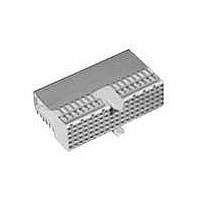
Conn Hard Metric F 110 POS 2mm Press Fit RA Thru-Hole
Manufacturer
Tyco Electronics
Type
Hard Metricr
Datasheet
1.352033-1.pdf
(84 pages)
Specifications of 646547-1
Pitch
2 mm
Number Of Rows
5
Number Of Contacts
110
Termination Method
Press Fit
Mounting
Through Hole
Contact Plating
Gold Over Nickel
Gender
Female
Housing Material
Glass Filled Polyester
Color
Gray
Mounting Angle
Right
Lead Free Status / Rohs Status
Lead free / RoHS Compliant


General Information
Layouts show connectors in a typical
stacking arrangement on a 2 x 2 [.079 x
.079] grid, with optional holes for
ground return shields.
Card extender or cable connector and
vertical female connectors use the same
5 row (a to e) layouts; ground return
shields are not used with these types.
Right Angle Connectors
Standard Version uses the board
layout as illustrated, right.
Reduced Crosstalk Version, with
metal plates between columns of con-
tacts, requires an additional pad (2.0 x
1.0 [.079 x .039]), or continuous path,
connected via row c, to the system
ground. Examples are shown below:
Symbols
Plated Through Holes:
Non-plated Through Holes:
Catalog 65911
Revised 7-05
www.tycoelectronics.com
Pad
e
Continuous path
Signal Contacts.
Row f odd
numbers for upper
ground return shield.
Row f even
numbers for lower
ground return shield.
Backplane
rows z and f.
Ø 2.0
polarizing, location peg hole
for press fit.
d
+ 0.1 -0
c
•
•
•
[.079
b
+ .004
Dimensions are in millimeters
and inches unless otherwise
specified. Values in brackets
are standard equivalents.
a
]
AMP Z-PACK 2mm HM Hard Metric
Interconnection System
Page_Head
PC Board Layout for 5/5+2 row Type A, B, C, Connectors and Ground Return Shields
Type A
Type B
Type C
See page 9 for details of plated through holes.
Column
2.0 [.079]
Row
4 x 2.0
[.315]
= 8.0
Male and Female Connector
10
11
12
13
14
15
16
17
18
19
20
21
22
23
24
25
10
11
12
13
14
15
16
17
18
19
20
21
22
23
24
25
10
11
1
2
3
4
5
6
7
8
9
1
2
3
4
5
6
7
8
9
1
2
3
4
5
6
7
8
9
Component Side
(Continued)
f e d c b a
Right Angle
reference purposes only.
Dimensions are shown for
Specifications subject
to change.
[.079]
2.0
[.079]
[.079]
[.079]
2.0
2.0
2.0
1.5 [.059]
8.0 [.315]
10 x 2.0
10 x 2.0
10 x 2.0
4.0 [.157]
24 x 2.0
Board Edge
= 20.0
= 20.0
= 20.0
[.787]
[.787]
[1.890]
[.787]
= 48.0
Note: For guidance only.
USA: 1-800-522-6752
Canada: 1-905-470-4425
Mexico: 01-800-733-8926
C. America: 52-55-5-729-0425
Consult customer
drawings for production
layouts
[1.890]
48.0
[1.968]
[1.968]
[.984]
50.0
25.0
50.0
Ø 2.0
[.079
2.0 [.079]
[.157]
4.0
+ 0.1 - 0
4 x 2.0
[.315]
[.118]
= 8.0
+ .004
3.0
Male and Female Connector
]
South America: 55-11-3611-1514
Hong Kong: 852-2735-1628
Japan: 81-44-844-8013
UK: 44-141-810-8967
z a b c d e f
Front Side
Vertical
Ø 2.0
[.079
2.0 [.079]
+ 0.1 - 0
10
11
12
13
14
15
16
17
18
19
20
21
22
23
24
25
10
11
12
13
14
15
16
17
18
19
20
21
22
23
24
25
10
11
+ .004
1
2
3
4
5
6
7
8
9
1
2
3
4
5
6
7
8
9
1
2
3
4
5
6
7
8
9
]
69
Related parts for 646547-1
Image
Part Number
Description
Manufacturer
Datasheet
Request
R

Part Number:
Description:
Battery Interconnection System for Portable Electronics; BU CONN FS6 8POS DIP TYPE ASSY ( AMP )
Manufacturer:
Tyco Electronics
Part Number:
Description:
Manufacturer:
Tyco Electronics
Datasheet:
Part Number:
Description:
Manufacturer:
Tyco Electronics
Datasheet:


