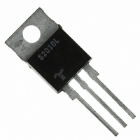
S2010L Littelfuse / Teccor Brand Thyristors, S2010L Datasheet - Page 8

S2010L
Manufacturer Part Number
S2010L
Description
SCR NON-SENS 200V 10A ISO TO-220
Manufacturer
Littelfuse / Teccor Brand Thyristors
Specifications of S2010L
Scr Type
Standard Recovery
Voltage - Off State
200V
Voltage - Gate Trigger (vgt) (max)
1.5V
Voltage - On State (vtm) (max)
1.6V
Current - On State (it (av)) (max)
6.4A
Current - On State (it (rms)) (max)
10A
Current - Gate Trigger (igt) (max)
15mA
Current - Hold (ih) (max)
30mA
Current - Off State (max)
10µA
Current - Non Rep. Surge 50, 60hz (itsm)
83A, 100A
Operating Temperature
-40°C ~ 125°C
Mounting Type
Through Hole
Package / Case
TO-220-3 (Isolated), ITO-220AB
Current - On State (it (rms) (max)
10A
Lead Free Status / RoHS Status
Lead free / RoHS Compliant
Available stocks
Company
Part Number
Manufacturer
Quantity
Price
Company:
Part Number:
S2010L
Manufacturer:
Littelfuse
Quantity:
135
Company:
Part Number:
S2010LS3
Manufacturer:
INFINEON
Quantity:
6 000
SCRs
Figure E6.7 Maximum Allowable Case Temperature versus
Figure E6.8 Maximum Allowable Case Temperature versus
Figure E6.9 Maximum Allowable Case Temperature versus
http://www.littelfuse.com
+1 972-580-7777
130
120
110
100
90
80
70
60
50
130
120
110
100
90
80
70
60
50
0
0
130
120
110
100
CURRENT WAVEFORM: Sinusoidal
LOAD: Resistive or Inductive
CONDUCTION ANGLE: 180˚
CASE TEMPERATURE: Measure as
shown on dimensional drawing
RMS On-state Current (10 A, 12 A, 16 A, and 20 A)
RMS On-state Current (25 A and 35 A)
RMS On-state Current (40 A through 70 A)
90
80
70
60
50
CURRENT WAVEFORM: Sinusoidal
LOAD: Resistive or Inductive
CONDUCTION ANGLE: 180 ˚
CASE TEMPERATURE: Measure
as shown on dimensional drawings
0
4
65 A TO-218X
10
4
RMS On-state Current [I
RMS On-state Current [I
(Isolated)
RMS On-state Current [I
8
20
55 A TO-218X
(Non-isolated)
(Non-isolated)
12
40 A TO-220
and TO-263
8
30
16
CURRENT WAVEFORM: Sinusoidal
LOAD: Resistive or Inductive
CONDUCTION ANGLE: 180˚
CASE TEMPERATURE: Measure as
shown on dimensional drawings
40
20
T(RMS)
T(RMS)
12
T(RMS)
] – Amps
24
50
] – Amps
] – Amps
70 A TO-218X
(Non-isolated)
28
60
16
32
70
36
20
E6 - 8
Figure E6.10 Maximum Allowable Case Temperature versus
Figure E6.11 Maximum Allowable Case Temperature versus
Figure E6.12 Maximum Allowable Case Temperature versus
130
120
110
100
90
80
130
120
110
100
90
80
70
60
50
0
0
RMS On-state Current (55 A and 65 A)
Average On-state Current (1 A)
Average On-state Current (8 A, 10 A, and 12 A)
* The R, K or M package rating
is intended only for high surge
condition use and is not recommended
for >50 A rms continuous
current use, since narrow pin lead
temperature can exceed PCB solder
melting temperature. J or W packages
are recommended for >50 A rms
continuous current requirements.
55 A TO-220
(Non-isolated)
and TO-263 *
130
120
110
100
90
80
70
60
50
1
10
0
Average On-state Current [I
CURRENT WAVEFORM: Sinusoidal
LOAD: Resistive or Inductive
CONDUCTION ANGLE: 180˚
CASE TEMPERATURE: Measure as
shown on dimensional drawings
Average On-state Current [I
RMS On-state Current [I
2
20
0.2
3
30
CURRENT WAVEFORM: Sinusoidal
LOAD: Resistive or Inductive
CONDUCTION ANGLE: 180˚
CASE TEMPERATURE: Measure as
shown on dimensional drawings
0.4
40
4
T(RMS)
CURRENT WAVEFORM: Sinusoidal
LOAD: Resistive or Inductive
CONDUCTION ANGLE: 180˚
CASE TEMPERATURE: Measure as
shown on dimensional drawings
10 A TO-220
(Non-isolated)
T(AV)
T(AV)
Thyristor Product Catalog
50
] – Amps
5
0.6
] – Amps
] – Amps
©2004 Littelfuse, Inc.
60
6
0.8
Data Sheets
70
7
75
8


