80RIA40 Vishay, 80RIA40 Datasheet - Page 6
80RIA40
Manufacturer Part Number
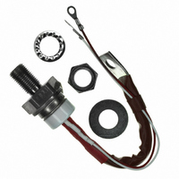
80RIA40
Description
SCR PHASE CONT 400V 125A TO-94
Manufacturer
Vishay
Datasheet
1.80RIA40.pdf
(7 pages)
Specifications of 80RIA40
Scr Type
Standard Recovery
Voltage - Off State
400V
Voltage - Gate Trigger (vgt) (max)
2.5V
Voltage - On State (vtm) (max)
1.6V
Current - On State (it (av)) (max)
80A
Current - On State (it (rms)) (max)
125A
Current - Gate Trigger (igt) (max)
120mA
Current - Hold (ih) (max)
150mA
Current - Off State (max)
15mA
Current - Non Rep. Surge 50, 60hz (itsm)
1900A, 1990A
Operating Temperature
-40°C ~ 125°C
Mounting Type
Chassis, Stud Mount
Package / Case
TO-209AC, TO-94
Current - On State (it (rms) (max)
125A
Breakover Current Ibo Max
1990 A
Rated Repetitive Off-state Voltage Vdrm
400 V
Off-state Leakage Current @ Vdrm Idrm
15 mA
Forward Voltage Drop
1.6 V
Gate Trigger Voltage (vgt)
2.5 V
Maximum Gate Peak Inverse Voltage
10 V
Gate Trigger Current (igt)
120 mA
Holding Current (ih Max)
200 mA
Mounting Style
Stud
Peak Repetitive Off-state Voltage, Vdrm
400V
Gate Trigger Current Max, Igt
120mA
Current It Av
80A
On State Rms Current It(rms)
125A
Peak Non Rep Surge Current Itsm 50hz
1.9kA
Lead Free Status / RoHS Status
Contains lead / RoHS non-compliant
Other names
*80RIA40
VS-80RIA40
VS-80RIA40
VS80RIA40
VS80RIA40
VS-80RIA40
VS-80RIA40
VS80RIA40
VS80RIA40


80RIA...PbF, 81RIA...PbF, 82RIA...PbF Series
Vishay Semiconductors
ORDERING INFORMATION TABLE
www.vishay.com
6
Dimensions
Device code
0.001
DiodesAmericas@vishay.com, DiodesAsia@vishay.com,
0.01
100
0.1
0.1
0.0001
10
For technical questions within your region, please contact one of the following:
0.001
1
1
Rectangular gate pulse
a) Recommended load line for
b) Recommended load line for
Steady State Value
R
(DC Operation)
tr<=1 µs
<=30% rated di/dt : 20V, 65ohms
VGD
thJC
rated di/dt : 20V, 30ohms; tr<=0.5 µs
= 0.30 K/W
IGD
0.01
1
2
3
4
5
6
0.001
Fig. 8 - Thermal Impedance Z
8
1
-
-
-
-
-
-
LINKS TO RELATED DOCUMENTS
Phase Control Thyristors
Device: 80RIA Series
0
2
Fig. 9 - Gate Characteristics
(Stud Version), 80 A
S q uare Wave Pulse Duration (s)
0.1
I
RIA = Essential part number
Voltage code x 100 = V
Lead (Pb)-free
TAV
Instantaneous Gate Current (A)
0 = Eyelet terminals (gate and auxiliary cathode leads)
1 = Fast-on terminals (gate and auxiliary cathode leads)
2 = Flag terminals (gate and auxiliary cathode terminals)
None = Stud base 1/2"-20UNF- 2 A threads
M = Stud base metric threads M12 x 1.75 E 6
(b)
0.01
x 10 A
RIA
3
(a)
1
120
4
thJC
0.1
80RIA Series
Characteristics
Frequency Limited by PG(AV)
M
10
5
(1) PGM = 100W, tp = 500µs
(2) PGM = 50W, tp = 1ms
(3) PGM = 20W, tp = 2.5ms
(4) PGM = 10W, tp = 5ms
(1) (2)
RRM
DiodesEurope@vishay.com
(see Voltage Ratings table)
PbF
6
www.vishay.com/doc?95362
(3)
1
100
(4)
1000
10
Document Number: 94392
Revision: 17-Sep-10
Related parts for 80RIA40
Image
Part Number
Description
Manufacturer
Datasheet
Request
R

Part Number:
Description:
357-036-542-201 CARDEDGE 36POS DL .156 BLK LOPRO
Manufacturer:
Vishay
Datasheet:
Part Number:
Description:
357-036-542-201 CARDEDGE 36POS DL .156 BLK LOPRO
Manufacturer:
Vishay
Datasheet:
Part Number:
Description:
357-036-542-201 CARDEDGE 36POS DL .156 BLK LOPRO
Manufacturer:
Vishay
Datasheet:
Part Number:
Description:
357-036-542-201 CARDEDGE 36POS DL .156 BLK LOPRO
Manufacturer:
Vishay
Datasheet:
Part Number:
Description:
357-036-542-201 CARDEDGE 36POS DL .156 BLK LOPRO
Manufacturer:
Vishay
Datasheet:
Part Number:
Description:
357-036-542-201 CARDEDGE 36POS DL .156 BLK LOPRO
Manufacturer:
Vishay
Datasheet:
Part Number:
Description:
357-036-542-201 CARDEDGE 36POS DL .156 BLK LOPRO
Manufacturer:
Vishay
Datasheet:
Part Number:
Description:
357-036-542-201 CARDEDGE 36POS DL .156 BLK LOPRO
Manufacturer:
Vishay
Datasheet:
Part Number:
Description:
357-036-542-201 CARDEDGE 36POS DL .156 BLK LOPRO
Manufacturer:
Vishay
Datasheet:
Part Number:
Description:
357-036-542-201 CARDEDGE 36POS DL .156 BLK LOPRO
Manufacturer:
Vishay
Datasheet:
Part Number:
Description:
357-036-542-201 CARDEDGE 36POS DL .156 BLK LOPRO
Manufacturer:
Vishay
Datasheet:
Part Number:
Description:
357-036-542-201 CARDEDGE 36POS DL .156 BLK LOPRO
Manufacturer:
Vishay
Datasheet:
Part Number:
Description:
357-036-542-201 CARDEDGE 36POS DL .156 BLK LOPRO
Manufacturer:
Vishay
Datasheet:
Part Number:
Description:
357-036-542-201 CARDEDGE 36POS DL .156 BLK LOPRO
Manufacturer:
Vishay
Datasheet:
Part Number:
Description:
357-036-542-201 CARDEDGE 36POS DL .156 BLK LOPRO
Manufacturer:
Vishay
Datasheet: