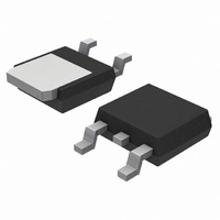
MCR8DCNT4G ON Semiconductor, MCR8DCNT4G Datasheet - Page 3

MCR8DCNT4G
Manufacturer Part Number
MCR8DCNT4G
Description
THYRISTOR SCR 8A 800V DPAK-4
Manufacturer
ON Semiconductor
Datasheet
1.MCR8DCMT4G.pdf
(5 pages)
Specifications of MCR8DCNT4G
Scr Type
Standard Recovery
Voltage - Off State
800V
Voltage - Gate Trigger (vgt) (max)
1V
Voltage - On State (vtm) (max)
1.8V
Current - On State (it (av)) (max)
5.1A
Current - On State (it (rms)) (max)
8A
Current - Gate Trigger (igt) (max)
15mA
Current - Hold (ih) (max)
30mA
Current - Off State (max)
10µA
Current - Non Rep. Surge 50, 60hz (itsm)
80A @ 60Hz
Operating Temperature
-40°C ~ 125°C
Mounting Type
Surface Mount
Package / Case
DPak, TO-252 (2 leads+tab), SC-63
Current - On State (it (rms) (max)
8A
Breakover Current Ibo Max
80 A
Rated Repetitive Off-state Voltage Vdrm
800 V
Off-state Leakage Current @ Vdrm Idrm
0.01 mA
Forward Voltage Drop
1.8 V
Gate Trigger Voltage (vgt)
1 V
Gate Trigger Current (igt)
15 mA
Holding Current (ih Max)
30 mA
Mounting Style
SMD/SMT
Lead Free Status / RoHS Status
Lead free / RoHS Compliant
Other names
MCR8DCNT4G
MCR8DCNT4GOSTR
MCR8DCNT4GOSTR
Available stocks
Company
Part Number
Manufacturer
Quantity
Price
Company:
Part Number:
MCR8DCNT4G
Manufacturer:
ON
Quantity:
12 500
Part Number:
MCR8DCNT4G
Manufacturer:
ON/安森美
Quantity:
20 000
125
120
105
100
115
110
100
Symbol
V
I
V
I
V
I
1.0
0.1
DRM
RRM
H
10
DRM
RRM
TM
0
0
TYPICAL @ T
V
Figure 1. Average Current Derating
T
1.0
I
, INSTANTANEOUS ON−STATE VOLTAGE (VOLTS)
Figure 3. On−State Characteristics
T(AV)
Parameter
Peak Repetitive Off State Forward Voltage
Peak Forward Blocking Current
Peak Repetitive Off State Reverse Voltage
Peak Reverse Blocking Current
Peak On State Voltage
Holding Current
1.0
a = 30°
, AVERAGE ON−STATE CURRENT (AMPS)
J
= 25°C
2.0
MAXIMUM @ T
2.0
3.0
60°
J
= 25°C
3.0
Voltage Current Characteristic of SCR
90°
MAXIMUM @ T
4.0
a = Conduction
120°
MCR8DCM, MCR8DCN
4.0
Angle
5.0
J
a
180°
http://onsemi.com
= 125°C
dc
6.0
5.0
I
Reverse Avalanche Region
RRM
Anode −
Reverse Blocking Region
3
at V
0.01
1.0
0.1
RRM
8.0
6.0
4.0
2.0
(off state)
10
0
0.1
0
a = Conduction
Figure 4. Transient Thermal Response
on state
Figure 2. On−State Power Dissipation
Angle
a = 30°
1.0
I
T(AV)
1.0
a
+ Current
, AVERAGE ON−STATE CURRENT (AMPS)
2.0
Forward Blocking Region
I
H
10
60°
t, TIME (ms)
V
TM
(off state)
3.0
I
DRM
100
90°
Z
qJC(t)
Anode +
4.0
at V
120°
= R
DRM
qJC(t)
1000
+ Voltage
5.0
Sr(t)
180°
dc
10 K
6.0


