10TTS08S Vishay, 10TTS08S Datasheet - Page 4
10TTS08S
Manufacturer Part Number
10TTS08S
Description
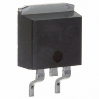
SCR PHASE CONTROL 800V 10A D2PAK
Manufacturer
Vishay
Specifications of 10TTS08S
Scr Type
Standard Recovery
Voltage - Off State
800V
Voltage - Gate Trigger (vgt) (max)
1V
Voltage - On State (vtm) (max)
1.15V
Current - On State (it (av)) (max)
6.5A
Current - On State (it (rms)) (max)
10A
Current - Gate Trigger (igt) (max)
15mA
Current - Hold (ih) (max)
30mA
Current - Off State (max)
50µA
Current - Non Rep. Surge 50, 60hz (itsm)
140A @ 50Hz
Operating Temperature
-40°C ~ 125°C
Mounting Type
Surface Mount
Package / Case
D²Pak, TO-263 (2 leads + tab)
Current - On State (it (rms) (max)
10A
Breakover Current Ibo Max
140 A
Rated Repetitive Off-state Voltage Vdrm
800 V
Off-state Leakage Current @ Vdrm Idrm
0.05 mA
Forward Voltage Drop
1.15 V
Gate Trigger Voltage (vgt)
1 V
Maximum Gate Peak Inverse Voltage
10 V
Gate Trigger Current (igt)
15 mA
Holding Current (ih Max)
30 mA
Mounting Style
SMD/SMT
Lead Free Status / RoHS Status
Contains lead / RoHS non-compliant
Other names
*10TTS08S
VS-10TTS08S
VS-10TTS08S
VS10TTS08S
VS10TTS08S
VS-10TTS08S
VS-10TTS08S
VS10TTS08S
VS10TTS08S
Available stocks
Company
Part Number
Manufacturer
Quantity
Price
Company:

Part Number:
10TTS08S
Manufacturer:
IR
Quantity:
12 500
Company:
Part Number:
10TTS08STRR
Manufacturer:
IR
Quantity:
12 500


Document Number: 93691
10TTS08S
Preliminary Data Sheet I2145 12/97
Number Of Equal Amplitude Half Cycle Current Pul s es (N)
Fig. 6 - Maximum Non-Repetitive Surge Current
130
120
110
100
125
120
115
110
105
Fig. 3 - On-state Power Loss Characteristics
90
80
70
60
8
7
6
5
4
3
2
1
0
0
1
0
Fig. 1 - Current Rating Characteristics
At Any Rated Load Condition And With
Rated V
10TTS08
RMS Limit
1
1
Average On-state Current (A)
Average On-state Current (A)
180°
120°
90°
60°
30°
2
2
RRM
30°
Applied Following Surge.
3
3
10TTS08
R
IR
10
thJC
60°
Conduction Angle
4
4
Conduction Angle
(DC) = 1.5 K/W
@ 60 Hz 0.0083 s
@ 50 Hz 0.0100 s
Series
Initial T = 125°C
90°
10TTS08
T = 125°C
J
5
5
120°
J
6
6
180°
100
7
7
Fig. 7 - Maximum Non-Repetitive Surge Current
125
120
115
110
105
150
140
130
120
110
100
Fig. 4 - On-state Power Loss Characteristics
12
10
90
80
70
60
50
8
6
4
2
0
0.01
0
0
Fig. 2 - Current Rating Characteristics
RMS Limit
Of Conduction May Not Be Maintained.
Maximum Non Repetitive Surge Current
10TTS08
180°
120°
Average On-state Current (A)
Average On-state Current (A)
DC
90°
60°
30°
2
2
Versus Pulse Train Duration. Control
30°
Pulse Train Duration (s)
10TTS08
R
60°
thJC
4
4
90°
(DC) = 1.5 K/W
Rated V
No Voltage Reapplied
120°
0.1
6
6
Conduction Period
www.vishay.com
Conduction Period
180°
10TTS08
T = 125°C
Initial T = 125°C
J
RRM
8
8
DC
Reapplied
J
10
10
4
12
12
1
Related parts for 10TTS08S
Image
Part Number
Description
Manufacturer
Datasheet
Request
R

Part Number:
Description:
357-036-542-201 CARDEDGE 36POS DL .156 BLK LOPRO
Manufacturer:
Vishay
Datasheet:
Part Number:
Description:
357-036-542-201 CARDEDGE 36POS DL .156 BLK LOPRO
Manufacturer:
Vishay
Datasheet:
Part Number:
Description:
357-036-542-201 CARDEDGE 36POS DL .156 BLK LOPRO
Manufacturer:
Vishay
Datasheet:
Part Number:
Description:
357-036-542-201 CARDEDGE 36POS DL .156 BLK LOPRO
Manufacturer:
Vishay
Datasheet:
Part Number:
Description:
357-036-542-201 CARDEDGE 36POS DL .156 BLK LOPRO
Manufacturer:
Vishay
Datasheet:
Part Number:
Description:
357-036-542-201 CARDEDGE 36POS DL .156 BLK LOPRO
Manufacturer:
Vishay
Datasheet:
Part Number:
Description:
357-036-542-201 CARDEDGE 36POS DL .156 BLK LOPRO
Manufacturer:
Vishay
Datasheet:
Part Number:
Description:
357-036-542-201 CARDEDGE 36POS DL .156 BLK LOPRO
Manufacturer:
Vishay
Datasheet:
Part Number:
Description:
357-036-542-201 CARDEDGE 36POS DL .156 BLK LOPRO
Manufacturer:
Vishay
Datasheet:
Part Number:
Description:
357-036-542-201 CARDEDGE 36POS DL .156 BLK LOPRO
Manufacturer:
Vishay
Datasheet:
Part Number:
Description:
357-036-542-201 CARDEDGE 36POS DL .156 BLK LOPRO
Manufacturer:
Vishay
Datasheet:
Part Number:
Description:
357-036-542-201 CARDEDGE 36POS DL .156 BLK LOPRO
Manufacturer:
Vishay
Datasheet:
Part Number:
Description:
357-036-542-201 CARDEDGE 36POS DL .156 BLK LOPRO
Manufacturer:
Vishay
Datasheet:
Part Number:
Description:
357-036-542-201 CARDEDGE 36POS DL .156 BLK LOPRO
Manufacturer:
Vishay
Datasheet:
Part Number:
Description:
357-036-542-201 CARDEDGE 36POS DL .156 BLK LOPRO
Manufacturer:
Vishay
Datasheet: