UMG4N-7 Diodes Inc, UMG4N-7 Datasheet
UMG4N-7
Manufacturer Part Number
UMG4N-7
Description
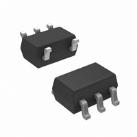
TRANS ARRAY DUAL SOT-353
Manufacturer
Diodes Inc
Datasheet
1.UMG4N-7.pdf
(3 pages)
Specifications of UMG4N-7
Transistor Type
2 NPN - Pre-Biased (Dual)
Current - Collector (ic) (max)
100mA
Voltage - Collector Emitter Breakdown (max)
50V
Resistor - Base (r1) (ohms)
10K
Dc Current Gain (hfe) (min) @ Ic, Vce
100 @ 1mA, 5V
Vce Saturation (max) @ Ib, Ic
300mV @ 1mA, 10mA
Frequency - Transition
250MHz
Power - Max
150mW
Mounting Type
Surface Mount
Package / Case
SC-70-5, SC-88A, SOT-323-5, SOT-353, 5-TSSOP
Lead Free Status / RoHS Status
Lead free / RoHS Compliant
Current - Collector Cutoff (max)
-
Resistor - Emitter Base (r2) (ohms)
-


Mechanical Data
Features
Maximum Ratings
Thermal Characteristics
Electrical Characteristics
Collector-Base Voltage
Collector-Emitter Voltage
Emitter-Base Voltage
Collector Current
Power Dissipation @T
Thermal Resistance, Junction to Ambient Air @T
Operating and Storage Temperature Range
Collector-Base Breakdown Voltage
Collector-Emitter Breakdown Voltage
Emitter-Base Breakdown Voltage
Collector Cut-Off Current
Emitter Cut-Off Current
Collector-Emitter Saturation Voltage
DC Current Gain
Gain-Bandwidth Product (Note 4)
Input Resistance
•
•
•
•
•
•
•
•
•
•
•
•
•
Notes:
DS31207 Rev. 3 - 2
Epitaxial Planar Die Construction
Surface Mount Package Suited for Automated Assembly
Simplifies Circuit Design and Reduces Board Space
Lead Free/RoHS Compliant (Note 1)
"Green" Device (Note 2)
Case: SOT-353
Case Material: Molded Plastic. UL Flammability
Classification Rating 94V-0
Moisture Sensitivity: Level 1 per J-STD-020C
Terminal Connections: See Diagram
Terminals: Finish – Matte Tin Annealed Over Alloy 42
Leadframe. Solderable per MIL-STD-202, Method 208
Marking Information: See Page 2
Ordering Information: See Page 2
Weight: 0.006 grams (approximate)
1. No purposefully added lead.
2. Diodes Inc.'s "Green" policy can be found on our website at http://www.diodes.com/products/lead_free/index.php.
3. Device mounted on FR-4 PCB; pad layout as shown on Diodes Inc. suggested pad layout document AP02001, which can be found on our website at
4. Characteristics of transistor. For reference only.
http://www.diodes.com/datasheets/ap02001.pdf.
A
Characteristic
= 25°C (Note 3)
Characteristic
Characteristic
@T
A
= 25°C unless otherwise specified
@T
A
= 25°C unless otherwise specified
A
= 25°C (Note 3)
V
V
V
Symbol
V
www.diodes.com
(BR)CBO
(BR)CEO
(BR)EBO
CE(SAT)
I
I
h
CBO
EBO
R
f
FE
T
1
1 of 3
Symbol
Symbol
T
Min
100
3
4
5.0
50
50
⎯
⎯
⎯
⎯
TOP VIEW
V
V
V
j
7
R
, T
P
CBO
CEO
EBO
I
θ JA
C
D
STG
2
Typ
330
250
Schematic and Pin Configuration
10
⎯
⎯
⎯
⎯
⎯
⎯
1
5
DUAL NPN PRE-BIASED TRANSISTOR
Max
600
0.5
0.5
0.3
13
⎯
⎯
⎯
⎯
SOT-353
-55 to +150
Unit
MHz
Value
Value
μA
μA
kΩ
⎯
100
150
833
V
V
V
V
50
50
5
(4)
R1
(3)
I
I
I
V
V
I
V
V
C
C
E
C
CB
EB
CE
CE
= 50μA, I
= 50μA, I
= 1mA, I
= 10mA, I
= 4V, I
= 50V, I
= 5V, I
= 10V, I
(2)
Test Condition
UMG4N
B
C
C
E
C
E
B
E
= 0
= 0
= 1mA
= 0
= 0
= 0
= 1mA
= -5mA, f = 100MHz
(1)
⎯
R1
(5)
© Diodes Incorporated
°C/W
Unit
Unit
mW
mA
°C
V
V
V
UMG4N
Related parts for UMG4N-7
Image
Part Number
Description
Manufacturer
Datasheet
Request
R

Part Number:
Description:
Diodes (General Purpose, Power, Switching) 240V 350mW
Manufacturer:
Diodes Inc
Datasheet:

Part Number:
Description:
Diodes (General Purpose, Power, Switching) -
Manufacturer:
Diodes Inc
Part Number:
Description:
Diodes (General Purpose, Power, Switching) -
Manufacturer:
Diodes Inc

Part Number:
Description:
Diodes (General Purpose, Power, Switching) NPN Small SIG 50V 45V VCEO 6.0V VEBO
Manufacturer:
Diodes Inc
Datasheet:
Part Number:
Description:
Diodes (General Purpose, Power, Switching) NPN Small SIG 30V 30V VCEO 5.0V VEBO
Manufacturer:
Diodes Inc
Datasheet:
Part Number:
Description:
Diodes (General Purpose, Power, Switching) NPN Small SIG -80V -65V VCEO -5.0 VEBO
Manufacturer:
Diodes Inc
Datasheet:
Part Number:
Description:
Diodes (General Purpose, Power, Switching) NPN Small SIG -50V -45V VCEO 6.0V VEBO
Manufacturer:
Diodes Inc
Part Number:
Description:
Diodes (General Purpose, Power, Switching) Dual Switching DIODE 100V Vrm 75Vrrm 53Vr
Manufacturer:
Diodes Inc
Datasheet:

Part Number:
Description:
Diodes (General Purpose, Power, Switching) Vr/80V Io/125mA T/R
Manufacturer:
Diodes Inc
Datasheet:

Part Number:
Description:
Diodes (General Purpose, Power, Switching) HV DUAL SW DIODE 300V
Manufacturer:
Diodes Inc
Datasheet:

Part Number:
Description:
Diodes (General Purpose, Power, Switching) 80V 150mW
Manufacturer:
Diodes Inc
Datasheet:
Part Number:
Description:
Diodes (General Purpose, Power, Switching) 75V 150mW
Manufacturer:
Diodes Inc
Datasheet:

Part Number:
Description:
Diodes (General Purpose, Power, Switching) 200MW 80V
Manufacturer:
Diodes Inc
Part Number:
Description:
Diodes (General Purpose, Power, Switching) 100V Io/150mA T/R INVALID P/N
Manufacturer:
Diodes Inc

Part Number:
Description:
Diodes (General Purpose, Power, Switching) 350MW 75V
Manufacturer:
Diodes Inc
UMG4N-7 Summary of contents
Page 1
... Max Unit Test Condition ⎯ 50μ ⎯ 1mA ⎯ 50μ μA 0 50V 0.5 μ 4V 0 10mA 1mA C B ⎯ 600 1mA CE C ⎯ MHz V = 10V -5mA 100MHz CE E ⎯ 13 kΩ © Diodes Incorporated UMG4N ...
Page 2
... I , COLLECTOR CURRENT (mA) C Fig. 1 Typical DC Current Gain vs. Collector Current Ordering Information (Note 5) Device UMG4N-7 Notes: 5. For packaging details our website at http://www.diodes.com/datasheets/ap02007.pdf. Marking Information Date Code Key Year 2007 Code U Month Jan Feb Code 1 2 DS31207 Rev ...
Page 3
... DS31207 Rev Dim M L All Dimensions in mm IMPORTANT NOTICE LIFE SUPPORT www.diodes.com SOT-353 Min Max A 0.10 0.30 B 1.15 1.35 C 2.00 2.20 D 0.65 Nominal F 0.30 0.40 H 1.80 2.20 ⎯ J 0.10 K 0.90 1.00 L 0.25 0.40 M 0.10 0.25 α 0° 8° © Diodes Incorporated UMG4N ...