5093NW1K000J08AFX Vishay, 5093NW1K000J08AFX Datasheet - Page 23
5093NW1K000J08AFX
Manufacturer Part Number
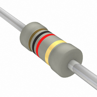
5093NW1K000J08AFX
Description
3W, 1K OHM, 5%
Manufacturer
Vishay
Series
PR03r
Datasheet
1.5093NW1R000J08AFX.pdf
(24 pages)
Specifications of 5093NW1K000J08AFX
Resistance (ohms)
1K
Power (watts)
3W
Composition
Metal Film
Features
Flame Retardant Coating
Temperature Coefficient
±250ppm/°C
Tolerance
±5%
Size / Dimension
0.205" Dia x 0.768" L (5.20mm x 19.50mm)
Lead Style
Through Hole
Package / Case
Axial
Resistance In Ohms
1.00K
Case
Axial
Lead Free Status / RoHS Status
Lead free / RoHS Compliant
Height
-
Lead Free Status / RoHS Status
Lead free / RoHS Compliant
Other names
2322 195 13102
232219513102
BC1.0KW-3TB
232219513102
BC1.0KW-3TB


BCcomponents
TESTS AND REQUIREMENTS
Essentially all tests are carried out in accordance with the
schedule of “IEC publication 60115-1”, category
LCT/UCT/56 (rated temperature range: Lower Category
Temperature, Upper Category Temperature; damp heat,
long term, 56 days). The testing also covers the requirements
specified by EIA and EIAJ.
The tests are carried out in accordance with IEC publication
60068-2, “Recommended basic climatic and mechanical
robustness testing procedure for electronic components”
and under standard atmospheric conditions according to
“IEC 60068-1”, subclause 5.3.
Table 7
2001 Jul 13
Tests in accordance with the schedule of IEC publication 60115-1
4.4.1
4.4.2
4.5
4.18
4.29
4.17
4.7
60115-1
CLAUSE
Professional power metal film resistors
IEC
Test procedures and requirements
20 (Tb)
45 (Xa)
20 (Ta)
METHOD
60068-2
TEST
IEC
visual examination
dimensions (outline) gauge (mm)
resistance
resistance to
soldering heat
component solvent
resistance
solderability
voltage proof on
insulation
TEST
applied voltage (+0/ 10%):
thermal shock: 3 s; 350 C;
6 mm from body
isopropyl alcohol or H
followed by brushing
in accordance with “MIL 202 F”
2 s; 235 C
maximum voltage 500 V (RMS)
during 1 minute; metal block method
R
10
100
1 k
10 k
100 k
R = 1 M : 50 V
10
R
R
R
R
R
0.1 V
PROCEDURE
23
10 k : 3 V
100
100 k : 10 V
1 k : 1 V
1 M : 25 V
In Table 7 the tests and requirements are listed with
reference to the relevant clauses of
“IEC publications 60115-1 and 60068-2”; a short
description of the test procedure is also given. In some
instances deviations from the IEC recommendations were
necessary for our method of specifying.
All soldering tests are performed with mildly activated flux.
: 0.3 V
2
O
no holes; clean surface;
no damage
see Tables 4, 5 and 6
R
no visual damage
good tinning; no damage
no breakdown or flashover
R/R max.: 1% + 0.05
R
nom
REQUIREMENTS
: max. 5%
PR01/02/03
Product specification
Related parts for 5093NW1K000J08AFX
Image
Part Number
Description
Manufacturer
Datasheet
Request
R

Part Number:
Description:
357-036-542-201 CARDEDGE 36POS DL .156 BLK LOPRO
Manufacturer:
Vishay
Datasheet:
Part Number:
Description:
357-036-542-201 CARDEDGE 36POS DL .156 BLK LOPRO
Manufacturer:
Vishay
Datasheet:
Part Number:
Description:
357-036-542-201 CARDEDGE 36POS DL .156 BLK LOPRO
Manufacturer:
Vishay
Datasheet:
Part Number:
Description:
357-036-542-201 CARDEDGE 36POS DL .156 BLK LOPRO
Manufacturer:
Vishay
Datasheet:
Part Number:
Description:
357-036-542-201 CARDEDGE 36POS DL .156 BLK LOPRO
Manufacturer:
Vishay
Datasheet:
Part Number:
Description:
357-036-542-201 CARDEDGE 36POS DL .156 BLK LOPRO
Manufacturer:
Vishay
Datasheet:
Part Number:
Description:
357-036-542-201 CARDEDGE 36POS DL .156 BLK LOPRO
Manufacturer:
Vishay
Datasheet:
Part Number:
Description:
357-036-542-201 CARDEDGE 36POS DL .156 BLK LOPRO
Manufacturer:
Vishay
Datasheet:
Part Number:
Description:
357-036-542-201 CARDEDGE 36POS DL .156 BLK LOPRO
Manufacturer:
Vishay
Datasheet:
Part Number:
Description:
357-036-542-201 CARDEDGE 36POS DL .156 BLK LOPRO
Manufacturer:
Vishay
Datasheet:
Part Number:
Description:
357-036-542-201 CARDEDGE 36POS DL .156 BLK LOPRO
Manufacturer:
Vishay
Datasheet:
Part Number:
Description:
357-036-542-201 CARDEDGE 36POS DL .156 BLK LOPRO
Manufacturer:
Vishay
Datasheet:
Part Number:
Description:
357-036-542-201 CARDEDGE 36POS DL .156 BLK LOPRO
Manufacturer:
Vishay
Datasheet:
Part Number:
Description:
357-036-542-201 CARDEDGE 36POS DL .156 BLK LOPRO
Manufacturer:
Vishay
Datasheet:
Part Number:
Description:
357-036-542-201 CARDEDGE 36POS DL .156 BLK LOPRO
Manufacturer:
Vishay
Datasheet: