MUN5137DW1T1 ON Semiconductor, MUN5137DW1T1 Datasheet
MUN5137DW1T1
Specifications of MUN5137DW1T1
Available stocks


Related parts for MUN5137DW1T1

MUN5137DW1T1 Summary of contents
Page 1
MUN5111DW1T1G Series Preferred Devices Dual Bias Resistor Transistors PNP Silicon Surface Mount Transistors with Monolithic Bias Resistor Network The Bias Resistor Transistor (BRT) contains a single transistor with a monolithic bias network consisting of two resistors; a series base resistor ...
Page 2
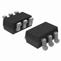
... MUN5134DW1T1G SOT−363 (Pb−Free) MUN5135DW1T1G SOT−363 (Pb−Free) MUN5136DW1T1G SOT−363 (Pb−Free) MUN5137DW1T1G SOT−363 (Pb−Free) †For information on tape and reel specifications, including part orientation and tape sizes, please refer to our Tape and Reel Packaging Specifications Brochure, BRD8011/D. Marking R1 (K) R2 (K) 0A ...
Page 3
... MUN5130DW1T1G MUN5131DW1T1G MUN5137DW1T1G MUN5115DW1T1G MUN5116DW1T1G MUN5132DW1T1G MUN5133DW1T1G MUN5134DW1T1G MUN5111DW1T1G h MUN5112DW1T1G MUN5113DW1T1G MUN5114DW1T1G MUN5115DW1T1G MUN5116DW1T1G MUN5130DW1T1G MUN5131DW1T1G MUN5132DW1T1G MUN5133DW1T1G MUN5134DW1T1G MUN5135DW1T1G MUN5136DW1T1G MUN5137DW1T1G http://onsemi.com 3 and Min Typ Max − − −100 CBO − − −500 CEO − − −0.5 EBO − ...
Page 4
... MUN5130DW1T1G MUN5131DW1T1G MUN5132DW1T1G MUN5133DW1T1G MUN5134DW1T1G MUN5135DW1T1G MUN5136DW1T1G MUN5137DW1T1G MUN5111DW1T1G R MUN5112DW1T1G MUN5113DW1T1G MUN5114DW1T1G MUN5115DW1T1G MUN5116DW1T1G MUN5130DW1T1G MUN5131DW1T1G MUN5132DW1T1G MUN5133DW1T1G MUN5134DW1T1G MUN5135DW1T1G MUN5136DW1T1G MUN5137DW1T1G http://onsemi.com 4 and Q ) (Continued Min Typ Max OL − − −0.2 − − −0.2 − − −0.2 − − −0.2 − ...
Page 5
ALL MUN5111DW1T1G SERIES DEVICES 300 250 200 150 100 R = 490°C/W 50 qJA 0 − AMBIENT TEMPERATURE (°C) A Figure 1. Derating Curve − ALL DEVICES http://onsemi.com 5 100 150 ...
Page 6
TYPICAL ELECTRICAL CHARACTERISTICS — MUN5111DW1T1G -25°C A 0.1 75°C 0. COLLECTOR CURRENT (mA) C Figure 2. V versus I CE(sat ...
Page 7
TYPICAL ELECTRICAL CHARACTERISTICS — MUN5112DW1T1G -25°C A 0.1 0. COLLECTOR CURRENT (mA) C Figure 7. V versus I CE(sat ...
Page 8
TYPICAL ELECTRICAL CHARACTERISTICS — MUN5113DW1T1G -25°C A 0.1 0. COLLECTOR CURRENT (mA) C Figure 12. V versus I CE(sat) 1 0.8 0.6 0.4 0 ...
Page 9
TYPICAL ELECTRICAL CHARACTERISTICS — MUN5114DW1T1G 0.1 75°C 0.01 0.001 COLLECTOR CURRENT (mA) C Figure 17. V versus I CE(sat) 4.5 4 3.5 3 2.5 2 1.5 1 ...
Page 10
TYPICAL ELECTRICAL CHARACTERISTICS — MUN5115DW1T1G 0.1 −25°C 25°C 0.01 0.001 COLLECTOR CURRENT (mA) C Figure 22. V versus I CE(sat ...
Page 11
TYPICAL ELECTRICAL CHARACTERISTICS — MUN5116DW1T1G 0.1 −25°C 25°C 0.01 0.001 COLLECTOR CURRENT (mA) C Figure 27. V versus I CE(sat ...
Page 12
TYPICAL ELECTRICAL CHARACTERISTICS — MUN5130DW1T1G 0.1 −25°C 25°C 0.01 0.001 COLLECTOR CURRENT (mA) C Figure 32. V versus I CE(sat) TBD V , REVERSE BIAS VOLTAGE (VOLTS) ...
Page 13
TYPICAL ELECTRICAL CHARACTERISTICS — MUN5131DW1T1G 0.1 −25°C 25°C 0.01 0.001 COLLECTOR CURRENT (mA) C Figure 37. V versus I CE(sat ...
Page 14
TYPICAL ELECTRICAL CHARACTERISTICS — MUN5132DW1T1G 0.1 −25°C 25°C 0.01 0.001 COLLECTOR CURRENT (mA) C Figure 42. V versus I CE(sat ...
Page 15
TYPICAL ELECTRICAL CHARACTERISTICS — MUN5133DW1T1G 0.1 −25°C 0.01 0.001 COLLECTOR CURRENT (mA) C Figure 47. V versus I CE(sat ...
Page 16
TYPICAL ELECTRICAL CHARACTERISTICS — MUN5134DW1T1G 75°C 0.1 −25°C 25°C 0.01 0.001 COLLECTOR CURRENT (mA) C Figure 52. V versus I CE(sat) 3.5 3 2.5 2 1.5 1 ...
Page 17
TYPICAL ELECTRICAL CHARACTERISTICS — MUN5135DW1T1G 0.1 −25°C 25°C 0.01 0.001 COLLECTOR CURRENT (mA) C Figure 57. V versus I CE(sat ...
Page 18
TYPICAL ELECTRICAL CHARACTERISTICS — MUN5136DW1T1G 1 0.1 −25°C 0. COLLECTOR CURRENT (mA) C Figure 62. V versus I CE(sat) 1.2 1.0 0.8 0.6 0.4 0 ...
Page 19
... TYPICAL ELECTRICAL CHARACTERISTICS — MUN5137DW1T1G −25°C A 0.1 25°C 0. COLLECTOR CURRENT (mA) C Figure 67. V versus I CE(sat) 1.4 1.2 1.0 0.8 0.6 0.4 0 REVERSE BIAS VOLTAGE (VOLTS) R Figure 69. Output Capacitance 100 10 25° Figure 71. Input Voltage versus Output Current 1000 75°C 100 ...
Page 20
... Pb−Free strategy and soldering details, please download the ON Semiconductor Soldering and Mounting Techniques Reference Manual, SOLDERRM/D. ON Semiconductor and are registered trademarks of Semiconductor Components Industries, LLC (SCILLC). SCILLC reserves the right to make changes without further notice to any products herein ...