BC847BT-7-F Diodes Inc, BC847BT-7-F Datasheet
BC847BT-7-F
Specifications of BC847BT-7-F
Available stocks


Related parts for BC847BT-7-F


BC847BT-7-F Summary of contents
Page 1
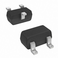
... Current Gain A 110 B h 200 FE C 420 (Note 3) — V CE(SAT) (Note 3) — V BE(SAT) 580 (Note — I CBO (Note 3) — I CBO 100 — OBO BC847BT NF — BC847CT www.diodes.com BC847AT, BT, CT SOT-523 Dim Min A 0. 1.45 D ⎯ G 0.90 H 1.50 J 0. 0.10 M 0.10 ...
Page 2
... I , COLLECTOR CURRENT (mA) C Fig. 3, Collector Saturation Voltage vs Collector Current Ordering Information (Note 4) Device BC847AT-7-F BC847BT-7-F BC847CT-7-F Notes: 4. For packaging details our website at http://www.diodes.com/datasheets/ap02007.pdf. Marking Information Date Code Key Year 1998 1999 2000 Code Month ...
Page 3
... Diodes Incorporated and its subsidiaries reserve the right to make modifications, enhancements, improvements, corrections or other changes without further notice to any product herein. Diodes Incorporated does not assume any liability arising out of the application or use of any product described herein; neither does it convey any license under its patent rights, nor the rights of others. The user of products in such applications shall assume all risks of such use and will agree to hold Diodes Incorporated and all the companies whose products are represented on our website, harmless against all damages ...