2N4401RLRPG ON Semiconductor, 2N4401RLRPG Datasheet - Page 5
2N4401RLRPG
Manufacturer Part Number
2N4401RLRPG
Description
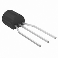
TRANS SS NPN GP 40V 600MA TO-92
Manufacturer
ON Semiconductor
Datasheet
1.2N4401RLRAG.pdf
(7 pages)
Specifications of 2N4401RLRPG
Transistor Type
NPN
Current - Collector (ic) (max)
600mA
Voltage - Collector Emitter Breakdown (max)
40V
Vce Saturation (max) @ Ib, Ic
750mV @ 50mA, 500mA
Dc Current Gain (hfe) (min) @ Ic, Vce
100 @ 150mA, 1V
Power - Max
625mW
Frequency - Transition
250MHz
Mounting Type
Through Hole
Package / Case
TO-92-3 (Standard Body), TO-226
Configuration
Single
Transistor Polarity
NPN
Mounting Style
Through Hole
Collector- Emitter Voltage Vceo Max
40 V
Emitter- Base Voltage Vebo
6 V
Continuous Collector Current
0.6 A
Maximum Dc Collector Current
0.6 A
Power Dissipation
625 mW
Maximum Operating Frequency
250 MHz
Maximum Operating Temperature
+ 150 C
Dc Collector/base Gain Hfe Min
20 at 0.1 mA at 1 V
Minimum Operating Temperature
- 55 C
Number Of Elements
1
Collector-emitter Voltage
40V
Collector-base Voltage
60V
Emitter-base Voltage
6V
Collector Current (dc) (max)
600mA
Frequency (max)
250MHz
Operating Temp Range
-55C to 150C
Operating Temperature Classification
Military
Mounting
Through Hole
Pin Count
3
Package Type
TO-92
Lead Free Status / RoHS Status
Lead free / RoHS Compliant
Current - Collector Cutoff (max)
-
Lead Free Status / Rohs Status
Lead free / RoHS Compliant
Other names
2N4401RLRPGOSTB
Available stocks
Company
Part Number
Manufacturer
Quantity
Price
Company:

Part Number:
2N4401RLRPG
Manufacturer:
ON
Quantity:
102 000
Company:
Part Number:
2N4401RLRPG
Manufacturer:
ON Semiconductor
Quantity:
1


h
obtain these curves, a high−gain and a low−gain unit were
fe
This group of graphs illustrates the relationship between
300
200
100
and other “h” parameters for this series of transistors. To
7.0
5.0
3.0
2.0
1.0
0.7
0.5
0.3
0.2
70
50
30
20
10
0.1
0.1
0.2
0.2
Figure 13. Voltage Feedback Ratio
0.3
0.3
I
Figure 11. Current Gain
I
C
C
, COLLECTOR CURRENT (mA)
, COLLECTOR CURRENT (mA)
0.5 0.7 1.0
0.5 0.7 1.0
2N4401 UNIT 1
2N4401 UNIT 2
2.0 3.0
2.0
2N4401 UNIT 1
2N4401 UNIT 2
V
3.0
CE
= 10 Vdc, f = 1.0 kHz, T
5.0 7.0
5.0 7.0
http://onsemi.com
h PARAMETERS
10
10
5
5.0 k
2.0 k
1.0 k
selected from the 2N4401 lines, and the same units were
used to develop the correspondingly numbered curves on
each graph.
50 k
20 k
10 k
500
100
5.0
2.0
1.0
50
10
20
0.1
0.1
A
= 25°C
0.2
0.2
Figure 14. Output Admittance
Figure 12. Input Impedance
0.3
0.3
I
I
C
C
, COLLECTOR CURRENT (mA)
, COLLECTOR CURRENT (mA)
0.5 0.7 1.0
0.5 0.7 1.0
2N4401 UNIT 1
2N4401 UNIT 2
2.0 3.0
2.0 3.0
2N4401 UNIT 1
2N4401 UNIT 2
5.0 7.0
5.0 7.0
10
10
Related parts for 2N4401RLRPG
Image
Part Number
Description
Manufacturer
Datasheet
Request
R

Part Number:
Description:
This device is designed for use as a medium power amplifier and switch requiring collector currents up to 500 mA
Manufacturer:
Fairchild Semiconductor
Datasheet:

Part Number:
Description:
General Purpose Transitors NPN Silicon
Manufacturer:
On Semiconductor
Part Number:
Description:
ON Semiconductor [VOLTAGE REGULATOR]
Manufacturer:
ON Semiconductor
Datasheet:
Part Number:
Description:
357-036-542-201 CARDEDGE 36POS DL .156 BLK LOPRO
Manufacturer:
ON Semiconductor
Datasheet:
Part Number:
Description:
357-036-542-201 CARDEDGE 36POS DL .156 BLK LOPRO
Manufacturer:
ON Semiconductor
Datasheet:
Part Number:
Description:
357-036-542-201 CARDEDGE 36POS DL .156 BLK LOPRO
Manufacturer:
ON Semiconductor
Datasheet:
Part Number:
Description:
357-036-542-201 CARDEDGE 36POS DL .156 BLK LOPRO
Manufacturer:
ON Semiconductor
Datasheet:
Part Number:
Description:
357-036-542-201 CARDEDGE 36POS DL .156 BLK LOPRO
Manufacturer:
ON Semiconductor
Datasheet:
Part Number:
Description:
357-036-542-201 CARDEDGE 36POS DL .156 BLK LOPRO
Manufacturer:
ON Semiconductor
Datasheet:
Part Number:
Description:
357-036-542-201 CARDEDGE 36POS DL .156 BLK LOPRO
Manufacturer:
ON Semiconductor
Datasheet:
Part Number:
Description:
357-036-542-201 CARDEDGE 36POS DL .156 BLK LOPRO
Manufacturer:
ON Semiconductor
Datasheet:
Part Number:
Description:
357-036-542-201 CARDEDGE 36POS DL .156 BLK LOPRO
Manufacturer:
ON Semiconductor
Datasheet:
Part Number:
Description:
357-036-542-201 CARDEDGE 36POS DL .156 BLK LOPRO
Manufacturer:
ON Semiconductor
Datasheet:
Part Number:
Description:
Manufacturer:
ON Semiconductor
Datasheet: