MJF44H11G ON Semiconductor, MJF44H11G Datasheet
MJF44H11G
Manufacturer Part Number
MJF44H11G
Description
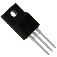
TRANS POWER NPN 10A 80V TO220FP
Manufacturer
ON Semiconductor
Type
Powerr
Specifications of MJF44H11G
Transistor Type
NPN
Current - Collector (ic) (max)
10A
Voltage - Collector Emitter Breakdown (max)
80V
Vce Saturation (max) @ Ib, Ic
1V @ 400mA, 8A
Current - Collector Cutoff (max)
1µA
Dc Current Gain (hfe) (min) @ Ic, Vce
40 @ 4A, 1V
Power - Max
2W
Frequency - Transition
50MHz
Mounting Type
Through Hole
Package / Case
TO-220-3 Full Pack (Straight Leads)
Transistor Polarity
NPN
Mounting Style
Through Hole
Collector- Emitter Voltage Vceo Max
80 V
Emitter- Base Voltage Vebo
5 V
Maximum Dc Collector Current
10 A
Power Dissipation
36 W
Maximum Operating Temperature
+ 150 C
Continuous Collector Current
10 A
Dc Collector/base Gain Hfe Min
60
Maximum Operating Frequency
50 MHz
Minimum Operating Temperature
- 55 C
Current, Collector
10 A
Current, Gain
40
Frequency
50 MHz
Package Type
TO-220
Polarity
NPN
Primary Type
Si
Resistance, Thermal, Junction To Case
3.5 °C/W
Voltage, Breakdown, Collector To Emitter
80 V
Voltage, Collector To Emitter
80 V
Voltage, Collector To Emitter, Saturation
1 V
Voltage, Emitter To Base
5 V
Lead Free Status / RoHS Status
Lead free / RoHS Compliant
Other names
MJF44H11GOS
Available stocks
Company
Part Number
Manufacturer
Quantity
Price
Company:

Part Number:
MJF44H11G
Manufacturer:
ON Semiconductor
Quantity:
1 500


Î Î Î Î Î Î Î Î Î Î Î Î
Î Î Î Î Î Î Î Î Î Î Î Î
Î Î Î Î Î Î Î Î Î Î Î Î
Î Î Î Î Î Î Î Î Î Î Î Î
Î Î Î Î Î Î Î Î Î Î Î Î
Î Î Î Î Î Î Î Î Î Î Î Î
Î Î Î Î Î Î Î Î Î Î Î Î
Î Î Î Î Î Î Î Î Î Î Î Î
Î Î Î Î Î Î Î Î Î Î Î Î
Î Î Î Î Î Î Î Î Î Î Î Î
Î Î Î Î Î Î Î Î Î Î Î Î
Î Î Î Î Î Î Î Î Î Î Î Î
Î Î Î Î Î Î Î Î Î Î Î Î
Î Î Î Î Î Î Î Î Î Î Î Î
Î Î Î Î Î Î Î Î Î Î Î Î
Î Î Î Î Î Î Î Î Î Î Î Î Î Î Î Î Î Î Î
Î Î Î Î Î Î Î Î Î Î Î Î Î Î Î Î Î Î Î
Î Î Î Î Î Î Î Î Î Î Î Î
Î Î Î Î Î Î Î Î Î Î Î Î
Î Î Î Î Î Î Î Î Î Î Î Î
Î Î Î Î Î Î Î Î Î Î Î Î
Î Î Î Î Î Î Î Î Î Î Î Î
Î Î Î Î Î Î Î Î Î Î Î Î
MJF44H11 (NPN),
MJF45H11 (PNP)
Complementary
Power Transistors
For Isolated Package Applications
amplification and switching such as output or driver stages in
applications such as switching regulators, converters and power
amplifiers.
Features
•
•
•
•
Maximum ratings are those values beyond which device damage can occur.
Maximum ratings applied to the device are individual stress limit values (not
normal operating conditions) and are not valid simultaneously. If these limits are
exceeded, device functional operation is not implied, damage may occur and
reliability may be affected.
*For additional information on our Pb−Free strategy and soldering details, please
MAXIMUM RATINGS
THERMAL CHARACTERISTICS
download the ON Semiconductor Soldering and Mounting Techniques
Reference Manual, SOLDERRM/D.
Collector−Emitter Voltage
Emitter−Base Voltage
Collector Current
Total Power Dissipation
Total Power Dissipation
Operating and Storage Junction
Thermal Resistance, Junction−to−Case
Thermal Resistance, Junction−to−Ambient
Complementary power transistors are for general purpose power
Low Collector−Emitter Saturation Voltage −
Fast Switching Speeds
Complementary Pairs Simplifies Designs
Pb−Free Packages are Available*
@ T
Derate above 25°C
@ T
Derate above 25°C
Temperature Range
A
C
= 25°C
= 25°C
Characteristic
Rating
− Continuous
− Peak
V
CE(sat)
Preferred Devices
= 1.0 V (Max) @ 8.0 A
Î Î Î
Î Î Î
Î Î Î
Î Î Î
Î Î Î
Î Î Î
Î Î Î
Î Î Î
Î Î Î
Î Î Î
Î Î Î
Î Î Î
Î Î Î
Î Î Î
Î Î Î
Î Î Î
Î Î Î
Î Î Î
Î Î Î
Î Î Î
Î Î Î
Symbol
Symbol
T
V
R
R
J
V
P
P
CEO
, T
I
qJC
qJA
EB
C
D
D
stg
Î Î Î Î
Î Î Î Î
Î Î Î Î
Î Î Î Î
Î Î Î Î
Î Î Î Î
Î Î Î Î
Î Î Î Î
Î Î Î Î
Î Î Î Î
Î Î Î Î
Î Î Î Î
Î Î Î Î
Î Î Î Î
Î Î Î Î
Î Î Î Î
Î Î Î Î
Î Î Î Î
Î Î Î Î
Î Î Î Î
Î Î Î Î
−55 to 150
Value
0.016
1.67
Max
62.5
2.0
3.5
80
10
20
36
5
Î Î Î
Î Î Î
Î Î Î
Î Î Î
Î Î Î
Î Î Î
Î Î Î
Î Î Î
Î Î Î
Î Î Î
Î Î Î
Î Î Î
Î Î Î
Î Î Î
Î Î Î
Î Î Î
Î Î Î
Î Î Î
Î Î Î
Î Î Î
Î Î Î
1
W/°C
W/°C
°C/W
°C/W
Unit
Unit
Vdc
Vdc
Adc
°C
W
W
Preferred devices are recommended choices for future use
and best overall value.
SILICON POWER TRANSISTORS
MJF44H11
MJF44H11G
MJF45H11
MJF45H11G
Device
1
F4xH11 = Specific Device Code
G
A
Y
WW
80 VOLTS, 36 WATTS
2
ORDERING INFORMATION
3
MARKING DIAGRAM
10 AMPERES
TO−220 FULLPACK
TO−220 FULLPACK
TO−220 FULLPACK
TO−220 FULLPACK
= Pb−Free Package
= Assembly Location
= Year
= Work Week
x = 4 or 5
(Pb−Free)
(Pb−Free)
F4xH11G
Package
ISOLATED TO−220
AYWW
CASE 221D
STYLE 2
50 Units/Rail
50 Units/Rail
50 Units/Rail
50 Units/Rail
Shipping
Related parts for MJF44H11G
Image
Part Number
Description
Manufacturer
Datasheet
Request
R

Part Number:
Description:
ON Semiconductor [VOLTAGE REGULATOR]
Manufacturer:
ON Semiconductor
Datasheet:
Part Number:
Description:
357-036-542-201 CARDEDGE 36POS DL .156 BLK LOPRO
Manufacturer:
ON Semiconductor
Datasheet:
Part Number:
Description:
357-036-542-201 CARDEDGE 36POS DL .156 BLK LOPRO
Manufacturer:
ON Semiconductor
Datasheet:
Part Number:
Description:
357-036-542-201 CARDEDGE 36POS DL .156 BLK LOPRO
Manufacturer:
ON Semiconductor
Datasheet:
Part Number:
Description:
357-036-542-201 CARDEDGE 36POS DL .156 BLK LOPRO
Manufacturer:
ON Semiconductor
Datasheet:
Part Number:
Description:
357-036-542-201 CARDEDGE 36POS DL .156 BLK LOPRO
Manufacturer:
ON Semiconductor
Datasheet:
Part Number:
Description:
357-036-542-201 CARDEDGE 36POS DL .156 BLK LOPRO
Manufacturer:
ON Semiconductor
Datasheet:
Part Number:
Description:
357-036-542-201 CARDEDGE 36POS DL .156 BLK LOPRO
Manufacturer:
ON Semiconductor
Datasheet:
Part Number:
Description:
357-036-542-201 CARDEDGE 36POS DL .156 BLK LOPRO
Manufacturer:
ON Semiconductor
Datasheet:
Part Number:
Description:
357-036-542-201 CARDEDGE 36POS DL .156 BLK LOPRO
Manufacturer:
ON Semiconductor
Datasheet:
Part Number:
Description:
357-036-542-201 CARDEDGE 36POS DL .156 BLK LOPRO
Manufacturer:
ON Semiconductor
Datasheet:
Part Number:
Description:
Manufacturer:
ON Semiconductor
Datasheet:
Part Number:
Description:
Manufacturer:
ON Semiconductor
Datasheet:
Part Number:
Description:
Manufacturer:
ON Semiconductor
Datasheet:
MJF44H11G Summary of contents
Page 1
... Pb−Free Package A = Assembly Location Y = Year WW = Work Week ORDERING INFORMATION Device Package MJF44H11 TO−220 FULLPACK 50 Units/Rail MJF44H11G TO−220 FULLPACK 50 Units/Rail (Pb−Free) MJF45H11 TO−220 FULLPACK 50 Units/Rail MJF45H11G TO−220 FULLPACK 50 Units/Rail (Pb−Free) Preferred devices are recommended choices for future use and best overall value. ...
Page 2
ELECTRICAL CHARACTERISTICS Î Î Î Î Î ...
Page 3
PACKAGE DIMENSIONS TO−220 FULLPAK CASE 221D−03 −B− −Y− 0.25 (0.010 ISSUE J NOTES: −T− SEATING 1. DIMENSIONING AND TOLERANCING PER ANSI ...