BC807-40W-7 Diodes Inc, BC807-40W-7 Datasheet
BC807-40W-7
Specifications of BC807-40W-7


Related parts for BC807-40W-7


BC807-40W-7 Summary of contents
Page 1
... Max Unit Test Condition V = -1.0V -100mA 250 CE C 400 600 — -1.0V -300mA — — — -500mA -50mA -0 -1.0V -300mA -1 -45V -100 -25V 150°C -5.0 µ -4.0V -100 -5.0V -10mA — MHz f = 50MHz V = -10V 1.0MHz BC807-16W / -25W / -40W Diodes Incorporated 8 ...
Page 2
... COLLECTOR-EMITTER VOLTAGE (V) CE Fig. 6, Typical Emitter-Collector Characteristics www.diodes.com T = 25° 20MHz -V = 5.0V CE 1.0V 10 100 1000 -I , COLLECTOR CURRENT (mA 150°C 25°C -50° 100 1000 -I , COLLECTOR CURRENT (mA) C 0.35 0.3 0.25 0.2 0.15 0 0.05mA BC807-16W / -25W / -40W ...
Page 3
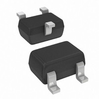
... Diodes Incorporated products are not authorized for use as critical components in life support devices or systems without the expressed written approval of the President of Diodes Incorporated. DS30577 Rev Packaging SOT-323 XXX = Product Type Marking Code (See Page 1), e.g. K5A = BC807- Date Code Marking Y = Year ex 2005 M = Month ex September 2006 ...