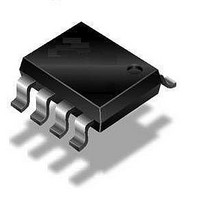
ATA6620N-TASY Atmel, ATA6620N-TASY Datasheet - Page 12

ATA6620N-TASY
Manufacturer Part Number
ATA6620N-TASY
Description
RF Wireless Misc LIN SBC
Manufacturer
Atmel
Datasheet
1.ATA6620N-TAQY.pdf
(22 pages)
Specifications of ATA6620N-TASY
Package / Case
SOIC
Mounting Style
SMD/SMT
Lead Free Status / RoHS Status
Lead free / RoHS Compliant
6. Voltage Regulator
12
ATA6620N
The voltage regulator needs an external capacitor for compensation and to smooth the distur-
bances from the microcontroller. It is recommend to use an tantalum capacitor with C > 10 µF
and a ceramic capacitor with C = 100 nF. The values of these capacitors can be varied by the
customer, depending on the application.
During mode change from Silent to Normal mode, the voltage regulator ramps up to 6V for only
a few microseconds before it drops back to 5V. This behavior depends on the value of the load
capacitor. With 4.7 µF, the overshoot voltage has its greatest value. This voltage decreases with
higher or lower load capacitors.
With this special SO8 package (fused lead frame to pin3) an R
Therefore it is recommended to connect pin 3 with a wide GND plate on the printed board to get
a good heat sink.
The main power dissipation of the IC is created from the V
needed for the application.
Figure 6-1
Figure 6-1.
For programming purposes of the microcontroller it is potentially necessary to supply the VCC
output via an external power supply while the VS pin of the system basis chip is disconnected.
This behavior is no problem for the system basis chip.
shows the safe operating area of the ATA6620N.
Save Operating Area versus V
ent Ambient Temperatures with R
60.00
40.00
30.00
20.00
50.00
10.00
0.00
5
6
7
8
9
10
11
V
S
12
(V)
CC
13
Output Current and Supply Voltage V
thja
14
= 80 K/W
15
16
17
thja
CC
18
of 80 K/W is achieved.
output current I
Iout_85: T
Iout_95: T
Iout_105: T
19
amb
amb
amb
= 85˚C
= 95˚C
= 105˚C
4850I–AUTO–09/09
VCC
S
, which is
at Differ-


