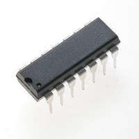
MC1496P ON Semiconductor, MC1496P Datasheet - Page 3

MC1496P
Manufacturer Part Number
MC1496P
Description
Modulator / Demodulator Balanced Mod/DeMod
Manufacturer
ON Semiconductor
Datasheet
1.MC1496DR2G.pdf
(14 pages)
Specifications of MC1496P
Package / Case
PDIP-14
Maximum Operating Temperature
+ 70 C
Maximum Power Dissipation
33 mW
Minimum Operating Temperature
0 C
Modulation Type
Balanced
Mounting Style
Through Hole
Supply Current
0.005 A
Lead Free Status / RoHS Status
Lead free / RoHS Compliant
Available stocks
Company
Part Number
Manufacturer
Quantity
Price
Company:
Part Number:
MC1496P
Manufacturer:
MOTOROLA
Quantity:
8
Part Number:
MC1496P
Manufacturer:
ON/安森美
Quantity:
20 000
Part Number:
MC1496PG
Manufacturer:
ON/安森美
Quantity:
20 000
1. T
ELECTRICAL CHARACTERISTICS
all input and output characteristics are single−ended, unless otherwise noted.) (Note 1)
Carrier Feedthrough
Carrier Suppression
Transadmittance Bandwidth (Magnitude) (R
Signal Gain (V
Single−Ended Input Impedance, Signal Port, f = 5.0 MHz
Single−Ended Output Impedance, f = 10 MHz
Input Bias Current
Input Offset Current
Average Temperature Coefficient of Input Offset Current
Output Offset Current (I6−I9)
Average Temperature Coefficient of Output Offset Current
Common−Mode Input Swing, Signal Port, f
Common−Mode Gain, Signal Port, f
Common−Mode Quiescent Output Voltage (Pin 6 or Pin 9)
Differential Output Voltage Swing Capability
Power Supply Current I6 +I12
Power Supply Current
DC Power Dissipation
I
bS
V
V
f
Carrier Input Port, V
Signal Input Port, V
Parallel Input Resistance
Parallel Input Capacitance
Parallel Output Resistance
Parallel Output Capacitance
I
(T
(T
low
S
ioS
|V
C
C
A
A
offset adjusted to zero
offset adjusted to zero
offset not adjusted
f
f
f
= 10 kHz, 300 mVrms
C
C
S
+ I1 ) I4
C
= 60 mVrms sine wave and
= 300 mVpp square wave:
= I1−I4; I
= −55°C to +125°C)
= −55°C to +125°C)
| = 0.5 Vdc
= 500 kHz, 60 mVrms sine wave
= 10 MHz, 60 mVrms sine wave
= 1.0 kHz, 300 mVrms sine wave
= 0°C for MC1496
= −40°C for MC1496B
2
S
ioC
= 100 mVrms, f = 1.0 kHz; | V
; I
= I8−I10
bC
S
+ I8 ) I10
C
= 300 mVrms sine wave
I14
= 60 mVrms sine wave
Characteristic
2
T
high
S
= 1.0 kHz, |V
= +70°C for MC1496
= +125°C for MC1496B
(V
CC
S
L
= 1.0 kHz
= 50 W)
= 12 Vdc, V
C
|= 0.5 Vdc)
f
f
f
f
C
C
C
C
C
= 1.0 kHz
= 10 MHz
= 1.0 kHz
= 1.0 kHz
|= 0.5 Vdc
http://onsemi.com
EE
= −8.0 Vdc, I5 = 1.0 mAdc, R
3
Fig.
10
10
10
5
5
8
6
6
7
7
7
7
7
9
9
7
7
Note
1
2
8
3
−
−
−
−
−
−
−
4
−
−
−
6
5
Symbol
⎥ TC
BW
⎥ TC
V
⎥ I
CMV
ACM
⎥ I
V
I
A
V
V
c
I
ioC
I
I
r
I
P
c
CFT
r
CC
bC
EE
L
op
bS
ioS
CS
VS
out
out
ip
oo
oo
ip
D
3dB
Ioo
Iio
= 3.9 kW, R
⎥
⎥
⎥
⎥
⎥
Min
2.5
40
−
−
−
−
−
−
−
−
−
−
−
−
−
−
−
−
−
−
−
−
−
−
−
−
−
e
= 1.0 kW, T
0.04
Typ
140
300
200
−85
3.5
2.0
5.0
0.7
0.7
2.0
5.0
8.0
8.0
2.0
3.0
40
20
65
50
80
40
12
12
14
90
33
A
Max
200
0.4
7.0
7.0
4.0
5.0
= T
30
30
80
−
−
−
−
−
−
−
−
−
−
−
−
−
−
−
−
−
−
low
to T
mVrms
mVrms
nA/°C
nA/°C
mAdc
MHz
Unit
Vpp
Vpp
Vpp
mW
V/V
high
kW
kW
dB
pF
pF
mA
mA
mA
dB
k
,


