T110D107M020AS Kemet, T110D107M020AS Datasheet - Page 2
T110D107M020AS
Manufacturer Part Number
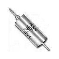
T110D107M020AS
Description
Tantalum Capacitors - Solid Leaded 20V 100uF 20%
Manufacturer
Kemet
Series
T110r
Datasheet
1.T110D107M020AS.pdf
(38 pages)
Specifications of T110D107M020AS
Tolerance (+ Or -)
20%
Voltage
20VDC
Esr
600mOhm
Mounting Style
Through Hole
Polarity
Polar
Construction
Axial
Case Style
Metal
Case Code
Not Required
Lead Spacing (nom)
Not Requiredmm
Df
6%
Dcl
10uA
Seal
Hermetic
Insulation
Sleeved
Failure Rate
Not Required
Wire Form
Not Required
Product Length (mm)
19.96mm
Product Height (mm)
Not Requiredmm
Product Depth (mm)
Not Requiredmm
Product Diameter (mm)
8.92mm
Seated Plane Height
Not Requiredmm
Length W/weld (max)
23.42mm
Operating Temp Range
-55C to 125C
Capacitance
100uF
Package / Case
Not Required
Voltage Rating
20 Volts
Tolerance
20 %
Termination Style
Axial
Operating Temperature Range
- 55 C to + 125 C
Dimensions
0.351 in Dia. x 0.786 in L
Product
Tantalum Solid Hermetically Sealed
Dissipation Factor Df
6
Leakage Current
10 uA
Lead Free Status / RoHS Status
Not Compliant


*Not approved to ‘D’ Failure Rate Level on all voltages and
capacitance values.
**MIL-PRF-39003/10 for space applications.
• CAPACITANCE/VOLTAGE RANGE:
• CAPACITANCE TOLERANCE: Available in stan-
• DISSIPATION FACTOR: Maximum DF limits are
• DC LEAKAGE CURRENT: Each corresponding
• RATED
• IMPEDANCE and ESR: See Application Notes
CSR09
CSR13* Polar-Standard MIL Case
CSS13** Polar-Standard MIL Case
CSR21
CSR23* Polar-Extended Range
.0023-1200µF, 6-125 Volts.
dard EIA values with ±20%, ±10% and ±5% toler-
ances.
shown in corresponding series part number list-
ings on pages 7-41. See Application Notes
Section, page 76 for additional description.
part number table lists maximum leakage current
for each capacitor on pages 7-41. See Application
Notes Section, page 76 for additional description.
SURGE VOLTAGE; REVERSE VOLTAGE: See
Application Notes Section, Pages 76 & 77 for
description.
Section, pages 77 & 78 for description. Reference
ESR values are shown for commercial hermetical-
ly sealed capacitors on page 19.
Polar-Subminiature
Polar-Standard Low ESR
MIL Case
VOLTAGE;
WORKING
T222
T212
T216
T262
T242
D (0.001%/k hrs.)
D (0.001%/k hrs.)
C (0.01%/k hrs.)
D (0.001%/k hrs.)
D (0.001%/k hrs.)
VOLTAGE;
*Not approved to ‘D’ Failure Rate Level on all voltages and
capacitance values.
**MIL-PRF-39003/10 for space applications.
CSR33* Polar-Extended Range
CSS33** Polar-Extended Range
CSR91* Non-Polar
• AC RIPPLE VOLTAGE: Permissible AC ripple volt-
• ENVIRONMENTAL CONSIDERATIONS:
For additional Environmental Test Information see
pages 80, 81 and 82.
• LEAD MATERIAL: Standard leads are solder-coat-
• INSULATING SLEEVES: The standard insulating
• LEAD TAPE and REEL: Reeling per specification
age is related to the ESR of the capacitor and the
power dissipation capabilities of a particular case
size. Thermal capacities for the various case sizes
have been determined empirically and are listed
below. For additional description see page 78.
A. Shock Test: MIL-STD-202, Method 213
B. Thermal Shock, MIL-STD-202,
C. Moisture Resistance: MIL-STD-202,
D. Solderability: MIL-STD-202, Method 208
ed nickel per MIL-STD-1276.
material used in transparent high temperature
plastic, having 2000 volt dielectric strength, excel-
lent dimensional stability and chemical and cold
flow resistance.
RS-296. See pages 71 and 73 for additional infor-
mation.
Method 107, Condition B.
Method 106.
Low Leakage
Low Leakage
A
B
C
D
.09
.100
.125
.180
T252
T256
T213
D (0.001%/k hrs.)
C (0.01%/k hrs.)
D (0.001%/k hrs.)
.070
.090
—
—
5
Related parts for T110D107M020AS
Image
Part Number
Description
Manufacturer
Datasheet
Request
R

Part Number:
Description:
CAP, KEMET #F601BL105K250C
Manufacturer:
Kemet
Datasheet:
Part Number:
Description:
Manufacturer:
Kemet
Datasheet:
Part Number:
Description:
Manufacturer:
Kemet
Datasheet: