CA2-B0-26-620-111-D Carling Technologies, CA2-B0-26-620-111-D Datasheet
CA2-B0-26-620-111-D
Specifications of CA2-B0-26-620-111-D


Related parts for CA2-B0-26-620-111-D


CA2-B0-26-620-111-D Summary of contents
Page 1
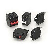
... Protectors, Supplementary for Marine Electrical & Fuel Systems (Guide PEQZ2, File E75596) Ignition Protection UL Listed UL Standard 489 Circuit Breakers, Molded Case, (Guide DIVQ, File E189195) UL Standard 489A Communications Equipment (Guide CCN/DITT, File E189195) 74 Designed for those applications requiring higher amperage and volt- age handling capability in a compact design ...
Page 2
Electrical Table A: Lists UL Recognized & CSA Accepted configurations and performance capabilities as a Component Supplementary Protector. Notes for Table A: 1 Requires branch circuit backup with a UL LISTED Type K5 or RK5 fuse rated 15A minimum and ...
Page 3
C-Series General Specifications Electrical Table B: Lists UL Recognized and CSA Accepted configurations and performance capabilities as a Manual Motor Controller. Notes for Table B: 1 Requires branch circuit backup with a UL LISTED Type K5 or RK5 fuse rated ...
Page 4
... Marine Electrical and Fuel Systems (Guide PEQZ2, File E75596). Ignition Protected per UL 1500. UL Classified Small Craft Electrical Devices, Marine in accordance with ISO 8846 (Guide UZMK, File MQ1515) as Marine Supplementary Protectors. Table F: Lists UL Listed configurations and performance capabilities as Circuit Breakers for use in Communications Equipment (Guide DITT, File E189195), under UL489A. www.carlingtech.com C-Series – ...
Page 5
... Mechanical Endurance 10,000 ON-OFF operations @ 6 per minute; with rated current & voltage. Trip Free All C-Series circuit breakers will trip on overload, even when actuator is forcibly held in the ON position. Trip Indication The operating actuator moves posi- tively to the OFF position when an overload causes the breaker to trip. ...
Page 6
Series Poles Aux/Alarm Actuator Circuit Switch 1 SERIES C 2 ACTUATOR 1 A Handle, one per pole B Handle, one per multipole unit S Mid-Trip Handle, one per pole ...
Page 7
C-Series Handle Parallel Pole UL489A Listed – Ordering — Series Poles Aux/Alarm Actuator Circuit Switch 1 SERIES C 2 ACTUATOR 1 A Handle, one per pole S Mid-Trip Handle, one ...
Page 8
... VDE approval on auxiliary switch codes 2, 3 & 4 only. Auxiliary / Alarm Switch with Independent Circuit ie: separate from breaker circuit, only available with circuit breakers rated 50 amp maximum at 80 VDC, 125 VDC, and 120 VAC. Auxiliary / Alarm Switch with Dependent Circuit ie: same as circuit breaker, is supplied from factory with common terminal of auxiliary / alarm switch connected to line terminal on 120/240 and 240 VAC ratings ...
Page 9
C-Series Sealed Toggle UL Recognized – Ordering Scheme — Poles Series Actuator Circuit 1 SERIES C 2 ACTUATOR 1 M Sealed Toggle, one per pole 3 POLES 1 One 2 Two ...
Page 10
Series Poles Actuator Circuit 1 SERIES C 2 ACTUATOR 1 Two Color Visi-Rocker Single color C Indicate ON, vertical legend J Vertical legend D Indicate ON, horizontal legend K Horizontal ...
Page 11
... Color shown is visi and legend with remainder of rocker black 10 Dual = ON-OFF/I-O legend on actuator. 11 VDE and TUV approval requires Dual (I-O, ON-OFF) markings on rocker. 12 Rockerguard available with all actuator codes. 13 Barriers supplied on multi-pole units only & 3 pole circuit breakers required for 120/240 AC rating. 84 — 14 — 450 — ...
Page 12
C — Series Actuator Poles Circuit 1 SERIES C 2 ACTUATOR 1 Two Color Visi-Rocker 1 Indicate OFF, vertical legend 2 Indicate OFF, horizontal legend Single color 3 Vertical legend 4 Horizontal ...
Page 13
... Legend on push-to-reset bezel/shroud matches visi-color of rocker with actuator codes 5 & Recessed “OFF-SIDE” available with actuator codes & 4. Legends on rocker are available in ink stamping only. 15 Barriers supplied on multi-pole units only & 3 pole circuit breakers required for 120/240 AC rating. 86 — 14 — 450 — 7 ...
Page 14
Notes: 1 All dimensions are in inches [millimeters]. 2 Tolerance ±.020 [.51] unless otherwise specified. 3 Available on Series Trip and Switch Only Circuits when called for on multi-pole units. Only one aux. switch is normally supplied, as viewed in ...
Page 15
C-Series Handle – Circuit & Terminal Diagrams Notes: 1 All dimensions are in inches [millimeters]. 2 Tolerance ±.020 [.51] unless otherwise specified. 3 Schematic shown represents current trip circuits. 4 Available only as special catalog number. 88 www.carlingtech.com ...
Page 16
Notes: 1 All dimensions are in inches [millimeters]. 2 Tolerance ±.020 [.51] unless otherwise specified. www.carlingtech.com C-Series Handle – Form & Fit Drawings 89 ...
Page 17
C-Series Handleguard – Form & Fit Drawings Notes: 1 All dimensions are in inches [millimeters]. 2 Tolerance ±.020 [.51] unless otherwise specified. 90 www.carlingtech.com ...
Page 18
Notes: 1 All dimensions are in inches [millimeters]. 2 Tolerance ±.020 [.51] unless otherwise specified. 3 Line and Load terminals must be paralleled with copper bus with a minimum cross sec- tion of .078 square inches [50.32 sq. mm.]. www.carlingtech.com ...
Page 19
C-Series Sealed Toggle – Form & Fit Drawings Notes: 1 All dimensions are in inches [millimeters]. 2 Tolerance ±.020 [.51] unless otherwise specified. 92 www.carlingtech.com ...
Page 20
Notes: 1 All dimensions are in inches [millimeters]. 2 Tolerance ±.020 [.51] unless otherwise specified. 3 Schematic shown represents current trip circuit. www.carlingtech.com C-Series Rocker – Circuit & Terminal Diagrams 93 ...
Page 21
C-Series Rocker – Form & Fit Drawings Notes: 1 Dimensions apply to all variations shown. Notice that circuit breaker line and load terminal orientation on indicate OFF is opposite of indicate ON. 2 For pole orientation with horizontal legend, rotate ...
Page 22
Notes: 1 For pole orientation with horizontal legend, rotate front view clockwise 90°. 2 All dimensions are in inches [millimeters]. 3 Tolerance ±.020 [.51] unless otherwise specified. www.carlingtech.com C-Series Flat Rocker – Form & Fit Drawings 95 ...