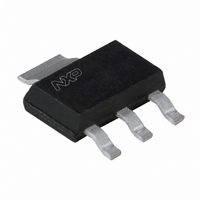
BSP61,115 NXP Semiconductors, BSP61,115 Datasheet - Page 4

BSP61,115
Manufacturer Part Number
BSP61,115
Description
TRANS PNP 80V 500MA SOT223
Manufacturer
NXP Semiconductors
Datasheet
1.BSP62115.pdf
(7 pages)
Specifications of BSP61,115
Package / Case
SOT-223 (3 leads + Tab), SC-73, TO-261
Mounting Type
Surface Mount
Power - Max
1.25W
Current - Collector (ic) (max)
1A
Voltage - Collector Emitter Breakdown (max)
60V
Transistor Type
PNP - Darlington
Current - Collector Cutoff (max)
50nA
Frequency - Transition
200MHz
Dc Current Gain (hfe) (min) @ Ic, Vce
2000 @ 500mA, 10V
Vce Saturation (max) @ Ib, Ic
1.3V @ 500µA, 500mA
Configuration
Single
Transistor Polarity
PNP
Mounting Style
SMD/SMT
Collector- Emitter Voltage Vceo Max
60 V
Emitter- Base Voltage Vebo
5 V
Collector- Base Voltage Vcbo
80 V
Maximum Dc Collector Current
1 A
Power Dissipation
1.25 W
Maximum Operating Temperature
+ 150 C
Continuous Collector Current
- 1 A
Dc Collector/base Gain Hfe Min
1000
Minimum Operating Temperature
- 65 C
Lead Free Status / RoHS Status
Lead free / RoHS Compliant
Other names
933986360115::BSP61 T/R::BSP61 T/R
NXP Semiconductors
2001 May 31
handbook, full pagewidth
PNP Darlington transistors
handbook, full pagewidth
V
V
R1 = 56 Ω; R2 = 10 kΩ; R
V
Oscilloscope: input impedance Z
CE
i
BB
= −10 V; T = 200 μs; t
h FE
= 1.8 V; V
= −10 V.
6000
5000
4000
3000
2000
1000
−10
0
−1
CC
= −10.7 V.
p
= 6 μs; t
B
= 10 kΩ; R
i
= 50 Ω.
r
= t
f
C
≤ 3 ns.
oscilloscope
= 18 Ω.
−1
V i
Fig.2 DC current gain; typical values.
Fig.3 Test circuit for switching times.
(probe)
450 Ω
R1
R2
R B
V BB
4
−10
R C
V CC
DUT
V o
MGD624
(probe)
450 Ω
BSP60; BSP61; BSP62
oscilloscope
−10
2
I C (mA)
Product data sheet
MGD839
−10
3


