MPS651RLRMG ON Semiconductor, MPS651RLRMG Datasheet - Page 3
MPS651RLRMG
Manufacturer Part Number
MPS651RLRMG
Description
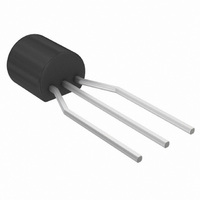
TRANS NPN SS 2A 60V TO92
Manufacturer
ON Semiconductor
Datasheet
1.MPS751RLRAG.pdf
(5 pages)
Specifications of MPS651RLRMG
Transistor Type
NPN
Current - Collector (ic) (max)
2A
Voltage - Collector Emitter Breakdown (max)
60V
Vce Saturation (max) @ Ib, Ic
500mV @ 200mA, 2A
Dc Current Gain (hfe) (min) @ Ic, Vce
75 @ 1A, 2V
Power - Max
625mW
Frequency - Transition
75MHz
Mounting Type
Through Hole
Package / Case
TO-92-3 (Standard Body), TO-226
Lead Free Status / RoHS Status
Lead free / RoHS Compliant
Current - Collector Cutoff (max)
-
Other names
MPS651RLRMGOS
Available stocks
Company
Part Number
Manufacturer
Quantity
Price
Company:

Part Number:
MPS651RLRMG
Manufacturer:
ON
Quantity:
16 000


0.05
0.02
0.01
2.0
1.8
1.6
1.4
1.2
1.0
0.8
0.6
0.4
0.2
1.0
0.9
0.8
0.7
0.6
0.5
0.4
0.3
0.2
0.1
4.0
2.0
1.0
0.5
0.2
0.1
10
0
0
0.05
1.0
50
0.1 0.2
I
C
T
A
= 10 mA I
2.0
= 25°C
V
CE
Figure 7. MPS650, MPS651 SOA,
100
, COLLECTOR−EMITTER VOLTAGE (VOLTS)
Collector Saturation Region
Figure 5. MPS650, MPS651
Figure 3. MPS650, MPS651
WIRE LIMIT
THERMAL LIMIT
SECOND BREAKDOWN LIMIT
0.5 1.0 2.0
I
C
, COLLECTOR CURRENT (mA)
C
Safe Operating Area
= 100 mA
I
B
200
5.0
, BASE CURRENT (mA)
On Voltages
V
NPN − MPS650, MPS651; PNP − MPS750, MPS751
BE(on)
V
NPN
NPN
NPN
BE(sat)
10
MPS65
I
MPS65
C
5.0 10 20
V
@ V
500
CE(sat)
= 500 mA
0
1
@ I
CE
T
C
1.0 ms
= 2.0 V
C
/I
@ I
20
B
= 25°C
1.0 A
= 10
C
/I
B
= 10
T
50 100 200 500
I
J
C
= 25°C
= 2.0 A
2.0 A
50
100 ms
http://onsemi.com
4.0 A
100
3
−0.05
−0.02
−0.01
−2.0
−1.8
−1.6
−1.4
−1.2
−1.0
−0.8
−0.6
−0.4
−0.2
−4.0
−2.0
−1.0
−0.5
−0.2
−0.1
−1.0
−0.9
−0.8
−0.7
−0.6
−0.5
−0.4
−0.3
−0.2
−0.1
−10
0
0
−0.05
−1.0
−50
−0.1 −0.2 −0.5 −1.0 −2.0 −5.0 −10 −20
I
T
C
A
−2.0
= −10 mA
= 25°C
V
Figure 8. MPS750, MPS751 SOA,
CE
−100
, COLLECTOR−EMITTER VOLTAGE (VOLTS)
Collector Saturation Region
Figure 4. MPS750, MPS751
Figure 6. MPS750, MPS751
WIRE LIMIT
THERMAL LIMIT
SECOND BREAKDOWN LIMIT
I
C
, COLLECTOR CURRENT (mA)
Safe Operating Area
I
−5.0
−200
B
, BASE CURRENT (mA)
I
C
On Voltages
= −100 mA
V
CE(sat)
PNP
PNP
PNP
−10
MPS75
V
MPS75
BE(sat)
0
−500
1
I
V
C
@ I
BE(on)
= −500 mA
1.0 ms
@ I
C
T
−20
C
/I
B
= 25°C
C
@ V
−1.0 A
= 10
/I
B
= 10
CE
−50 −100 −200 −500
= 2.0 V
−2.0 A
100 ms
T
−50
J
I
C
= 25°C
= −2.0 A
−4.0 A
−100
Related parts for MPS651RLRMG
Image
Part Number
Description
Manufacturer
Datasheet
Request
R

Part Number:
Description:
ON Semiconductor [VOLTAGE REGULATOR]
Manufacturer:
ON Semiconductor
Datasheet:
Part Number:
Description:
357-036-542-201 CARDEDGE 36POS DL .156 BLK LOPRO
Manufacturer:
ON Semiconductor
Datasheet:
Part Number:
Description:
357-036-542-201 CARDEDGE 36POS DL .156 BLK LOPRO
Manufacturer:
ON Semiconductor
Datasheet:
Part Number:
Description:
357-036-542-201 CARDEDGE 36POS DL .156 BLK LOPRO
Manufacturer:
ON Semiconductor
Datasheet:
Part Number:
Description:
357-036-542-201 CARDEDGE 36POS DL .156 BLK LOPRO
Manufacturer:
ON Semiconductor
Datasheet:
Part Number:
Description:
357-036-542-201 CARDEDGE 36POS DL .156 BLK LOPRO
Manufacturer:
ON Semiconductor
Datasheet:
Part Number:
Description:
357-036-542-201 CARDEDGE 36POS DL .156 BLK LOPRO
Manufacturer:
ON Semiconductor
Datasheet:
Part Number:
Description:
357-036-542-201 CARDEDGE 36POS DL .156 BLK LOPRO
Manufacturer:
ON Semiconductor
Datasheet:
Part Number:
Description:
357-036-542-201 CARDEDGE 36POS DL .156 BLK LOPRO
Manufacturer:
ON Semiconductor
Datasheet:
Part Number:
Description:
357-036-542-201 CARDEDGE 36POS DL .156 BLK LOPRO
Manufacturer:
ON Semiconductor
Datasheet:
Part Number:
Description:
357-036-542-201 CARDEDGE 36POS DL .156 BLK LOPRO
Manufacturer:
ON Semiconductor
Datasheet:
Part Number:
Description:
Manufacturer:
ON Semiconductor
Datasheet:
Part Number:
Description:
Manufacturer:
ON Semiconductor
Datasheet:
Part Number:
Description:
Manufacturer:
ON Semiconductor
Datasheet: