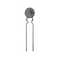
PTCCL09H541DTE Vishay, PTCCL09H541DTE Datasheet - Page 21

PTCCL09H541DTE
Manufacturer Part Number
PTCCL09H541DTE
Description
PTC CP LDD 8D50 A540 030 140 T E3
Manufacturer
Vishay
Series
661r
Type
PTCr
Specifications of PTCCL09H541DTE
Voltage - Max
30V
Current - Hold (ih) (max)
540mA
Current - Trip (it)
810mA
Current - Max
6A
Package / Case
Radial
Mounting Style
Through Hole
Pin Count
2
Screening Level
Industrial
Percentage Of Resistance Tolerance @ 25c
±20
Operating Temperature Min Deg. C
-40C
Operating Temperature Max Deg. C
85C
Product Length (mm)
Not Requiredmm
Product Height (mm)
Not Requiredmm
Product Depth (mm)
4mm
Lead Free Status / RoHS Status
Contains lead / RoHS non-compliant
R Min/max
-
Time To Trip
-
Lead Free Status / RoHS Status
Contains lead / RoHS non-compliant
Other names
2322 661 55411
232266155411
BC1341
PTCCL09H541DBC
232266155411
BC1341
PTCCL09H541DBC
BCcomponents
TESTS AND REQUIREMENTS
Clause numbers of tests and performance requirements refer to the CECC 44000 standard.
Inspection levels are selected from “IEC 60410”. Tables with requirements for lot-by-lot and periodic tests.
In these tables:
D = Destructive
ND = Non-destructive.
Acceptable quality level
2000 Oct 13
Group A inspection (lot-by-lot)
S
4.3.1
4.3.2
4.3.3
S
4.4
4.23
4.24
4.25
Group B inspection (lot-by-lot)
S
4.13.1
Group C inspection (periodic)
S
4.22.1
UB
UB
UB
UB
NUMBER
PTC thermistors for
overload protection
CLAUSE
-
-
-
-
GROUP
GROUP
GROUP
GROUP
A1
A2
B1
C1
visual examination
marking
dimensions (gauging)
zero power resistance
tripping current
non-tripping current
residual current at V
soldering, solderability
endurance (cycling)
TEST
max
ND
ND
D
D
D OR
ND
temperature: 25 C
measured at 25 C
measured at 25 C
measured at 25 C
solder bath method: 235 5 C
duration: 10 cycles
temperature: 25 C
voltage: as specified
I
cycle: 1 minute on and 9 minutes off
visual examination
zero power resistance at 25 C
duration: 10 cycles
temperature for:
voltage: as specified
I
cycle: 1 minute on and 9 minutes off
visual examination
zero power resistance at 25 C
max
max
30 and 60 V; 40 C
145 and 265 V; 0 C
: see Tables 3, 4, 5 and Fig.2
: see Tables 3, 4, 5 and Fig.2
21
CONDITIONS
30 to 60 V, 145 V and
265 V (T
no defect likely to
impair function
as specified
as specified
as specified
as specified
as specified
the leads shall be
evenly tinned
as in 4.20.1.8
as in 4.20.1.8
R/R:
R/R:
Product specification
s
PERFORMANCE
= 140 C)
10%
10%


