PTCTZ3NR339CTE Vishay, PTCTZ3NR339CTE Datasheet
PTCTZ3NR339CTE
Manufacturer Part Number
PTCTZ3NR339CTE
Description
PTC TE HOR 6D50 3R30 024 NTM T HM
Manufacturer
Vishay
Series
661r
Type
PTCr
Specifications of PTCTZ3NR339CTE
Voltage - Max
24V
Time To Trip
6s
Current - Hold (ih) (max)
400mA
Current - Trip (it)
650mA
Current - Max
8A
Package / Case
Non-Standard SMD
Description Of Terminals
Leadless
Mounting Style
Surface Mount
Pin Count
2
Resistance @ 25c
3.3Ohm
Percentage Of Resistance Tolerance @ 25c
±25
Product Length (mm)
7.2mm
Product Height (mm)
2mm
Product Depth (mm)
8mm
Resistance
3.3 Ohms
Tolerance
- 20 % to + 15 %
Termination Style
SMD/SMT
Current Rating
0.7 mAmp
Lead Free Status / RoHS Status
Contains lead / RoHS non-compliant
R Min/max
-
Lead Free Status / Rohs Status
Lead free / RoHS Compliant
Other names
2322 661 97013
232266197013
BC1567TR
PTCTZ3NR339CTX
232266197013
BC1567TR
PTCTZ3NR339CTX


Note
1. These types pass ITU-K20-21-45 edition 2003 telecommunication protection recommendation.
Notes
1. Customized products are available on request.
2. Coated and/or reinforced types are available on request.
Document Number: 29068
Revision: 07-Sep-04
Telecommunication types
General industrial types
ELECTRICAL DATA AND ORDERING INFORMATION
QUICK REFERENCE DATA
DESCRIPTION
Nominal R25
Resistance tolerance
Maximum overload current
(voltage dependent)
Non-trip current
Maximum voltage
Response time at 25 ° C and
20 W overload power
Matching
Maximum continuous power at
15 to 20
15 to 20
3.3
9.4
10
10
40
25
20
35
50
R
( Ω )
RESISTANCE
25
+15/ − 20
TOL
20
20
25
20
20
20
25
25
(%)
−
−
Horizontal Surface Mount PTC Thermistors
MATCHING
50 to 500 mA
0.5
0.5
0.5
STANDARD
no
no
no
TYPES
16 to 400 V
1
1
1
−
−
Ω
at 25 ° C
2 to 500
(RMS)
± 10%; ± 15%; ± 20%
−
For technical questions contact: nlr.europe@vishay.com
(1)(2)
For Overload Protection
2 to 10 A
VALUE
<1 s
2 W
MAX.
245
245
265
265
300
300
300
425
425
24
60
(V)
V
down to 0.5 Ω
50 to 100 mA
220 to 600 V
TYPES
TELECOM
at 70 ° C
10 to 70
( RMS)
25 ° C
(mA)
165
165
120
150
150
120
110
400
150
80
90
(1)(2)
I
nt
at
70 ° C
(mA)
100
100
100
100
100
50
70
70
70
60
−
FEATURES
• Ideal for pick-and-place circuit assembly
• Low mounting height
• Suitable for reflow soldering
• Small ceramic diameter for faster response
• Low heat transfer to substrate
• Flat terminations for stable positioning and good
APPLICATIONS
• Telecom
• General industry and automotive
DESCRIPTION
The component consists of a high-performance PTC
ceramic disc mounted in a lead-frame for direct soldering
onto a printed-circuit board (PCB) or substrate.
The ceramic is soldered to the leadframe by a local reflow
process, during which the solder layer is melted to the
metallized ceramic surface using a low residue flux.
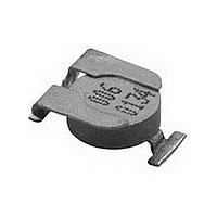
MARKING
• All SMD PTCs are marked with the last 3-digits of the type
solderability.
– Central office switching (C.O.)
– Subscriber terminal equipment (T.E.)
– Set top box
– Modems
– Cable TV communications
– Low power supplies overload protection
– Data bus protection.
number (XXX) and a date code (YYWW).
25 ° C
(mA)
270
270
130
220
250
250
250
175
150
650
300
I
t
at
TRIP-TIME
at 1 A (s)
MAX.
3.0
3.0
0.8
1.3
1.5
1.5
1.4
1.0
0.8
6.0
1.8
Vishay BCcomponents
2322 661 97...
V
I
max
max
2.0
2.0
2.0
2.0
1.5
2.0
1.5
0.7
0.7
8.0
3.0
(A)
at
www.vishay.com
2322 661 .....
CATALOG
NUMBER
97012
97016
97005
97004
97003
97018
97009
97013
97011
97002
97019
(1)
(1)
(1)
(1)
(1)
(1)
(1)
(1)
(1)
1
Related parts for PTCTZ3NR339CTE
Image
Part Number
Description
Manufacturer
Datasheet
Request
R

Part Number:
Description:
357-036-542-201 CARDEDGE 36POS DL .156 BLK LOPRO
Manufacturer:
Vishay
Datasheet:
Part Number:
Description:
357-036-542-201 CARDEDGE 36POS DL .156 BLK LOPRO
Manufacturer:
Vishay
Datasheet:
Part Number:
Description:
357-036-542-201 CARDEDGE 36POS DL .156 BLK LOPRO
Manufacturer:
Vishay
Datasheet:
Part Number:
Description:
357-036-542-201 CARDEDGE 36POS DL .156 BLK LOPRO
Manufacturer:
Vishay
Datasheet:
Part Number:
Description:
357-036-542-201 CARDEDGE 36POS DL .156 BLK LOPRO
Manufacturer:
Vishay
Datasheet:
Part Number:
Description:
357-036-542-201 CARDEDGE 36POS DL .156 BLK LOPRO
Manufacturer:
Vishay
Datasheet:
Part Number:
Description:
357-036-542-201 CARDEDGE 36POS DL .156 BLK LOPRO
Manufacturer:
Vishay
Datasheet:
Part Number:
Description:
357-036-542-201 CARDEDGE 36POS DL .156 BLK LOPRO
Manufacturer:
Vishay
Datasheet:
Part Number:
Description:
357-036-542-201 CARDEDGE 36POS DL .156 BLK LOPRO
Manufacturer:
Vishay
Datasheet:
Part Number:
Description:
357-036-542-201 CARDEDGE 36POS DL .156 BLK LOPRO
Manufacturer:
Vishay
Datasheet:
Part Number:
Description:
357-036-542-201 CARDEDGE 36POS DL .156 BLK LOPRO
Manufacturer:
Vishay
Datasheet:
Part Number:
Description:
357-036-542-201 CARDEDGE 36POS DL .156 BLK LOPRO
Manufacturer:
Vishay
Datasheet:
Part Number:
Description:
357-036-542-201 CARDEDGE 36POS DL .156 BLK LOPRO
Manufacturer:
Vishay
Datasheet:
Part Number:
Description:
357-036-542-201 CARDEDGE 36POS DL .156 BLK LOPRO
Manufacturer:
Vishay
Datasheet:
Part Number:
Description:
357-036-542-201 CARDEDGE 36POS DL .156 BLK LOPRO
Manufacturer:
Vishay
Datasheet:
PTCTZ3NR339CTE Summary of contents
Page 1
... For technical questions contact: nlr.europe@vishay.com 2322 661 97... Vishay BCcomponents MAX. CATALOG I at max TRIP-TIME NUMBER V (A) max (s) 2322 661 ..... 3.0 2.0 97012 3.0 2.0 97016 ...
Page 2
... Vapour phase soldering. 300 250 200 150 100 200 250 t (s) Typical values (solid line). Process limits (dotted lines). For technical questions contact: nlr.europe@vishay.com DESCRIPTION MATERIAL AND REMARKS ceramic BaTiO3 doped NiCr Ag layer metallization (vacuum deposition) Ni plated phosphor bronze material leadframe ...