Î Î Î Î Î Î Î Î Î Î Î Î Î Î Î Î Î Î Î
Î Î Î Î Î Î Î Î Î Î Î Î Î Î Î Î Î Î Î
Î Î Î Î Î Î Î Î Î Î Î
Î Î Î Î Î Î Î Î Î Î Î
Î Î Î Î Î Î Î Î Î Î Î
Î Î Î Î Î Î Î Î Î Î Î
Î Î Î Î Î Î Î Î Î Î Î
Î Î Î Î Î Î Î Î Î Î Î
Î Î Î Î Î Î Î Î Î Î Î
Î Î Î Î Î Î Î Î Î Î Î
Î Î Î Î Î Î Î Î Î Î Î
Î Î Î Î Î Î Î Î Î Î Î
Î Î Î Î Î Î Î Î Î Î Î
Î Î Î Î Î Î Î Î Î Î Î
Î Î Î Î Î Î Î Î Î Î Î
Î Î Î Î Î Î Î Î Î Î Î
Î Î Î Î Î Î Î Î Î Î Î
Î Î Î Î Î Î Î Î Î Î Î
Î Î Î Î Î Î Î Î Î Î Î
Î Î Î Î Î Î Î Î Î Î Î
Î Î Î Î Î Î Î Î Î Î Î
Î Î Î Î Î Î Î Î Î Î Î
Î Î Î Î Î Î Î Î Î Î Î
Î Î Î Î Î Î Î Î Î Î Î Î Î Î Î Î Î Î Î
Î Î Î Î Î Î Î Î Î Î Î Î Î Î Î Î Î Î Î
Î Î Î Î Î Î Î Î Î Î Î
Î Î Î Î Î Î Î Î Î Î Î
Î Î Î Î Î Î Î Î Î Î Î
Î Î Î Î Î Î Î Î Î Î Î
2N3771, 2N3772
High Power NPN Silicon
Power Transistors
regulators, and inductive switching applications.
Features
•
•
Stresses exceeding Maximum Ratings may damage the device. Maximum
Ratings are stress ratings only. Functional operation above the Recommended
Operating Conditions is not implied. Extended exposure to stresses above the
Recommended Operating Conditions may affect device reliability.
1. Indicates JEDEC registered data.
*For additional information on our Pb−Free strategy and soldering details, please
© Semiconductor Components Industries, LLC, 2006
October, 2006 − Rev. 11
MAXIMUM RATINGS
THERMAL CHARACTERISTICS
download the ON Semiconductor Soldering and Mounting Techniques
Reference Manual, SOLDERRM/D.
Collector−Emitter Voltage
Collector−Emitter Voltage
Collector−Base Voltage
Emitter−Base Voltage
Collector Current − Continuous
Base Current −
Total Device Dissipation @ T
Derate above 25°C
Operating and Storage Junction
Temperature Range
Thermal Resistance,
Junction−to−Case
These devices are designed for linear amplifiers, series pass
Forward Biased Second Breakdown Current Capability
Pb−Free Packages are Available*
I
S/b
Characteristic
= 2.5 Adc @ V
= 3.75 Adc @ V
Rating
Peak
Continuous
Peak
2N3771 is a Preferred Device
(Note 1)
C
CE
= 25°C
CE
= 60 Vdc − 2N3772
= 40 Vdc − 2N3771
Î Î Î
Î Î Î
Î Î Î
Î Î Î
Î Î Î
Î Î Î
Î Î Î
Î Î Î
Î Î Î
Î Î Î
Î Î Î
Î Î Î
Î Î Î
Î Î Î
Î Î Î
Î Î Î
Î Î Î
Î Î Î
Î Î Î
Î Î Î
Î Î Î
Î Î Î
Î Î Î
Î Î Î
Î Î Î
Symbol
Symbol
T
V
V
J
V
V
q
P
CEO
, T
CEX
I
I
CB
JC
EB
C
B
D
stg
Î Î Î
Î Î Î
Î Î Î
Î Î Î
Î Î Î
Î Î Î
Î Î Î
Î Î Î
Î Î Î
Î Î Î
Î Î Î
Î Î Î
Î Î Î
Î Î Î
Î Î Î
Î Î Î Î Î Î
Î Î Î Î Î Î
Î Î Î Î Î Î
Î Î Î Î Î Î
Î Î Î Î Î Î
Î Î Î Î Î Î
Î Î Î Î Î Î
Î Î Î Î Î Î
Î Î Î Î Î Î
Î Î Î Î Î Î
2N3771
5.0
7.5
40
50
50
30
30
15
– 65 to + 200
Î Î Î Î
Î Î Î Î
Î Î Î Î
Î Î Î Î
Î Î Î Î
Î Î Î Î
Î Î Î Î
Î Î Î Î
Î Î Î Î
Î Î Î Î
Î Î Î Î
Î Î Î Î
Î Î Î Î
Î Î Î Î
Î Î Î Î
0.855
Max
1.17
150
2N3772
100
7.0
5.0
60
80
20
30
15
1
Î Î Î Î
Î Î
Î Î
Î Î Î Î
Î Î Î Î
Î Î
Î Î
Î Î Î Î
Î Î
Î Î Î Î
Î Î
Î Î Î Î
Î Î Î Î
Î Î
Î Î Î Î
Î Î Î Î
W/°C
°C/W
Unit
Unit
Vdc
Vdc
Vdc
Vdc
Adc
Adc
°C
W
Preferred devices are recommended choices for future use
and best overall value.
2N3771
2N3771G
2N3772
2N3772G
40 and 60 VOLTS, 150 WATTS
Device
POWER TRANSISTORS
2N377x = Device Code
G
A
YY
WW
MEX
ORDERING INFORMATION
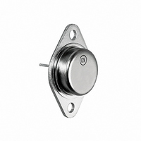
TO−204AA (TO−3)
20 and 30 AMPERE
CASE 1−07
http://onsemi.com
STYLE 1
NPN SILICON
(Pb−Free)
(Pb−Free)
Package
TO−204
TO−204
TO−204
TO−204
= Pb−Free Package
= Assembly Location
= Year
= Work Week
= Country of Origin
x = 1 or 2
Publication Order Number:
100 Units / Tray
100 Units / Tray
100 Units / Tray
100 Units / Tray
MARKING
DIAGRAM
2N377xG
AYYWW
Shipping
MEX
2N3771/D