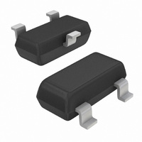
MMBT2907ALT1 ON Semiconductor, MMBT2907ALT1 Datasheet - Page 4

MMBT2907ALT1
Manufacturer Part Number
MMBT2907ALT1
Description
TRANS SS GP PNP 60V SOT23
Manufacturer
ON Semiconductor
Datasheet
1.MMBT2907ALT1G.pdf
(6 pages)
Specifications of MMBT2907ALT1
Transistor Type
PNP
Current - Collector (ic) (max)
600mA
Voltage - Collector Emitter Breakdown (max)
60V
Vce Saturation (max) @ Ib, Ic
1.6V @ 50mA, 500mA
Dc Current Gain (hfe) (min) @ Ic, Vce
100 @ 150mA, 10V
Power - Max
225mW
Frequency - Transition
200MHz
Mounting Type
Surface Mount
Package / Case
SOT-23-3, TO-236-3, Micro3™, SSD3, SST3
Transistor Polarity
PNP
Power Dissipation Pd
300mW
Dc Collector Current
600mA
Dc Current Gain Hfe
300
No. Of Pins
3
C-e Breakdown Voltage
-60V
Power (ptot)
300mW
Peak Reflow Compatible (260 C)
No
Rohs Compliant
No
Lead Free Status / RoHS Status
Contains lead / RoHS non-compliant
Current - Collector Cutoff (max)
-
Other names
MMBT2907ALT1OSCT
Available stocks
Company
Part Number
Manufacturer
Quantity
Price
Company:
Part Number:
MMBT2907ALT1
Manufacturer:
ON
Quantity:
7 553
Company:
Part Number:
MMBT2907ALT1
Manufacturer:
ON
Quantity:
2 600
Part Number:
MMBT2907ALT1
Manufacturer:
ON/安森美
Quantity:
20 000
Company:
Part Number:
MMBT2907ALT1G
Manufacturer:
ON
Quantity:
126 000
Company:
Part Number:
MMBT2907ALT1G
Manufacturer:
ON
Quantity:
30 000
Part Number:
MMBT2907ALT1G
Manufacturer:
ON/安森美
Quantity:
20 000
Part Number:
MMBT2907ALT1HTSA1
Manufacturer:
INFINEON原装
Quantity:
20 000
8.0
6.0
4.0
2.0
7.0
5.0
3.0
2.0
10
30
20
10
0.01
-0.1
0
0.01
0.1
1
0.001
Figure 11. Collector Emitter Saturation Voltage
0.02 0.05 0.1 0.2
-0.2 -0.3 -0.5
I
C
/I
B
= 10
Figure 7. Frequency Effects
I
C
Figure 9. Capacitances
I
-500 mA, R
-50 mA, R
-100 mA, R
REVERSE VOLTAGE (VOLTS)
, COLLECTOR CURRENT (A)
C
vs. Collector Current
= -1.0 mA, R
f, FREQUENCY (kHz)
0.01
-1.0
R
0.5 1.0 2.0
s
s
s
s
= 2.7 kW
= OPTIMUM SOURCE RESISTANCE
C
= 560 W
= 1.6 kW
eb
-2.0 -3.0 -5.0
s
= 430 W
TYPICAL SMALL−SIGNAL Characteristics
25°C
5.0 10
0.1
150°C
-10
20
−55°C
V
CE
http://onsemi.com
-20 -30
50 100
NOISE FIGURE
C
= 10 Vdc, T
cb
1
4
A
400
300
200
100
8.0
6.0
4.0
2.0
10
80
60
40
30
20
= 25°C
1.1
1.0
0.9
0.8
0.7
0.6
0.5
0.4
0.3
0.2
0
-1.0 -2.0
50
Figure 10. Current−Gain − Bandwidth Product
0.001
Figure 12. Base Emitter Saturation Voltage vs.
100
I
C
Figure 8. Source Resistance Effects
/I
f = 1.0 kHz
−55°C
150°C
B
25°C
200
= 10
V
T
-5.0
CE
J
= 25°C
R
I
= -20 V
s
I
C
C
, SOURCE RESISTANCE (OHMS)
, COLLECTOR CURRENT (mA)
, COLLECTOR CURRENT (A)
I
-100 mA
-500 mA
-1.0 mA
-10
500 1.0 k 2.0 k
C
0.01
= -50 mA
Collector Current
-20
-50
-100 -200
5.0 k 10 k
0.1
20 k
-500 -1000
50 k
1


