RC2010FK-0710ML Yageo, RC2010FK-0710ML Datasheet - Page 3
RC2010FK-0710ML
Manufacturer Part Number
RC2010FK-0710ML
Description
Resistor
Manufacturer
Yageo
Series
PRC111r
Datasheet
1.RC2010FK-071ML.pdf
(8 pages)
Specifications of RC2010FK-0710ML
Resistance
10Mohm
Resistance Tolerance
± 1%
Resistor Element Material
Thick Film
Resistor Case Style
2010
Power Rating
500mW
Voltage Rating
200V
Temperature Coefficient
± 200ppm/°C
Lead Free Status / RoHS Status
Lead free / RoHS Compliant


Sep 16, 2004 V.2
CONSTRUCTION
The resistors are constructed out of
a high-grade ceramic body. Internal
metal electrodes are added at each
end and connected by a resistive
paste. The composition of the paste
is adjusted to give the approximate
required resistance and laser cutting
of this resistive layer that achieves
tolerance trims the value. The
resistive layer is covered with a
protective coat and printed with the
resistance value. Finally, the two external terminations (pure Tin) are added. See fig. 3.
DIMENSIONS
MARKING
For marking codes, please see EIA-marking code rules in data sheet “Chip resistors instruction”.
RC2010
TYPE
L (mm)
W (mm)
H (mm)
I
I
1
2
(mm)
(mm)
Table 1
Fig. 1
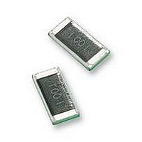
Fig. 2 Value=10 KΩ
Value=10 KΩ
Chip Resistor Surface Mount
ynsc001
ynsc004
5.00 ±0.10
2.50 ±0.15
0.55 ±0.10
0.45 ±0.15
0.50 ±0.20
RC2010
E-24 series: 3 digits
First two digits for significant figure and 3rd digit for number of zeros
Both E-24 and E-96 series: 4 digits
First three digits for significant figure and 4th digit for number of zeros
Fig. 3 Chip resistor construction
Fig. 4 Chip resistor dimension
handbook, 4 columns
RC
W
H
SERIES
I 2
I
1
2010 (Pb Free)
L
protective coat
resistor layer
inner electrode
end termination
ceramic substrate
protective coat
For dimension see Table 1
Product specification
www.yageo.com
MBE940_a
3
3
Related parts for RC2010FK-0710ML
Image
Part Number
Description
Manufacturer
Datasheet
Request
R

Part Number:
Description:
RES SMD 2010 4K75 1% 0.75W TC100 7 Reel
Manufacturer:
Yageo
Datasheet:

Part Number:
Description:
Resistor
Manufacturer:
Yageo
Datasheet:

Part Number:
Description:
Resistor
Manufacturer:
Yageo
Datasheet:
Part Number:
Description:
RESISTOR, PRC111 2010 6M8
Manufacturer:
Yageo
Datasheet:
Part Number:
Description:
RESISTOR, PRC111 2010 2M2
Manufacturer:
Yageo
Datasheet:
Part Number:
Description:
Resistor
Manufacturer:
Yageo
Datasheet:
Part Number:
Description:
Resistor
Manufacturer:
Yageo
Datasheet:
Part Number:
Description:
Resistor
Manufacturer:
Yageo
Datasheet:

Part Number:
Description:
YAGEO 22pF ±5% 50V NPO
Manufacturer:
Yageo
Datasheet: